
This is one of several attempts at writing the"ZX81 BASIC on the Minstrel 4th" blog post. It went on too long and into too much detail. I decided to start again and wrote a new version, the one you hopefully saw a few weeks ago.
I decided to finish it off and add the missing pictures and even some flowcharts and post it to my Patreon. Now it's your turn, and as a bonous, I have added some extra colourful diagrams.

I will warn you now, this is going to be a long blog post.
I've written a lot of it now when it's fresh, and before I forget how it works.
A while ago, I looked into getting ZX80 BASIC working on the Minstrel 4D, and had some success, it was mostly working. Loading and saving were going to be a problem because of the SD card interface on the Minstrel 4D which only understood Jupiter Ace format. It also relied on typing commands into the Ace for loading, which would be the wrong thing to type on BASIC so I would have to find a way to make that work.
I was also using ZX80 BASIC as a step to the actual goal of getting ZX81 BASIC working on there.
Roll on to now and the 4th is back and has a standard tape interface, so that simplifies things.
Lets have another go at ZX81 BASIC.
How hard can it be?
Very, as it turns out.
How the ZX80 Generates Video
Quick refresher. If you want to generate a video signal without a dedicated video chip, you have to sit there bit bashing and counting cycles to make sure your timing is correct.
One way around that is to stop the processor using the HALT command, and sit there doing nothing* until something triggers a low level on the INT pin and wakes the processor up again.
* When halted, the Z80 does not run any instructions, but it does have a mechanism for refreshing dynamic RAM which means it generates reads of each byte of RAM in turn, controlled by a few special registers. This happens all the time, normally when the Z80 has read an instruction and is working on it, the refresh happens in the background.
I won't go into great detail here (he lied), but for each horizontal line on the screen, the ZX80 draws the pixels of any characters that appear on that line, and then executes a HALT instruction and goes to sleep until a counter reaches the end of the line and triggers an interrupt to wake up the Z80. It then gets ready for the next line and repeat until the display is drawn.
The clever thing about the ZX80 is that is uses the refresh mechanism in the Z80 to read the display information, and that is also the counter that actually wakes the Z80 back up at the end of the line. To do this, the A6 address line is hard wired to the interrupt pin!
At the top of the screen there is a vertical sync section to tell the monitor a new frame is about to start. This is where the ZX80 scans the keyboard etc. and it does that in a way that always takes the same number of cycles to get the required timing.
The ZX80 display is ingenious and convoluted. Getting the most out of minimal hardware and software and RAM.
The display is stored in the main RAM, and operates in two modes. To save RAM, it starts with a "collapsed" display file. This only contains characters when it needs to. There is a newline character after the right most character than should be displayed, and on blank lines, there is just the newline character.
That means the display file can be as small as 26 bytes, or when fully populated, 793 bytes.
The next two screenshots are borrowed from an old post:
It uses the grey background mode of the Minstrel 2 to show where characters are not being drawn. The Z80 is halted for most of the area that is greyed out.

The other mode is "expanded" display file. Here every line is 32 characters long plus a newline character. This extra character for each line ironically wastes more space than if they have simply memory mapped the whole display as 32x24 characters, which would have needed 768 bytes instead.

Here the Z80 is working to draw all the characters, including the blank ones, and is only halted at the ends of the lines.
The display file can also be anywhere within RAM.
How the Minstrel 4th Generates Video
The Minstrel 4th hardware is very different to the ZX80. A6 is not hard wired to IRQ for a start. It does have an interrupt, but this comes once every frame, rather than once every line.
Video is generated by a CRTC microcontroller (CRT (Cathode Ray Tube) Controller.
The display is also very differently formatted. The Minstrel 4th has a memory mapped display, with it's own dedicated memory, handily in a place the ZX80 doesn't normally access. This is a straightforward 32x24 block of memory.
This display RAM is on a dual port RAM chip, the Z80 accesses one side of it, and the CRTC chip accesses the other. The CRTC reads through every character in the display RAM and generates a composite video signal from that.
The Minstrel 4th CRTC chip knows nothing of the ZX80 format, or where to find the display file in RAM, so how is that going to work?
Well, the ZX80 is already dedicated to spend most of its time drawing a display, it just needs to generate it in a different way. Rather than directly generating composite video, it will be locating and parsing the display file and writing out the characters to the Minstrel 4th video RAM. (which will be busy generating a display on the other side of the dual port RAM)
This takes less time that it would take to draw the frame, so it can simply* replace the normal display routine and run every frame to keep the Minstrel 4th video RAM up to date (well, one frame behind).
(* "simply", he said, rather optimistically)
One "feature" of the ZX80 is that is has to stop drawing the screen when it goes away to do other things. This creates the characteristic flickering on the display when you type characters.
There is no flicker here, as video RAM stops being updated when in "fast" mode, but the Minstrel 4th video chip is still running unaware of this and continues to display the previous screen.
(later I added code to fill the screen with 50% grey characters when in "fast" mode so it does not look like it has locked up)

That was working well, there were various issues I fixed, such as the LOAD and SAVE routines, keyboard scanner and adding support for "flicker free" games etc. These were covered in the previous posts.
I managed to squeeze in one more update to the Minstrel 4th before the first orders went out the door.
ZX81 BASIC
The Minstrel 4th can now run ZX81 8K ROM floating point BASIC, and it can do it reasonably well.
My criteria (as it often seems to be) is "can it play 3D Monster Maze". And the answer is yes, it can.

This infamously christened "fast" mode as "the mists of time".
Slow mode is better than fast mode. It sounds odd, so I will do a quick recap for those sitting at the back, not paying attention.
The ZX80 only worked in "fast" mode. In that mode, the ZX80 was either drawing the screen OR it was running code. It couldn't maintain the screen whilst running code, and would flicker each time you pressed a key (it has to run code to handle a keypress), or your program would go away and think for a bit and the screen would go away until it was finished.
This flickering was not ideal, and the ZX81 introduced "slow" mode. Which was better. Yeah, maybe a bad naming choice?
Anyway, in "slow" mode, the ZX81 can draw the screen AND run code. However, it can only run the code for some of the time (the top and bottom borders of the screen to be precise), so it runs slower than if it was in fast mode, about a third of the speed.
This used a Non-Maskable Interrupt to interrupt user code to draw the screen and scan the keyboard and then return. Here you can see the sections where the NMI Generator is enabled (all the signals shown are active low), an NMI signal is generated every time there is a horizontal sync pulse. This means out of each 20ms frame, the Z80 is running user code for about 7ms, so about a third of the time. (it is less than that as it is interrupted each line to check if it is finished the border, so it works out about 6ms per frame)

The times when the NMI generator is not active, there is an standard interrupt every line to setup the magic for the next line, just like the ZX80.
A lot of this is implemented in hardware in the ZX81.

The Minstrel 4th does not have any of that, so how did I do it?
Well, what the Minstrel 4th does have is an interrupt, but rather than being every line as on the ZX81, it is every frame. And there is no NMI, and no NMI generator.
I had started with the ZX80, as that was easier to deal with, not having the "slow" mode.
I had changed the display code in the ZX80 ROM. It now gets an interrupt at the start of every frame, allowing it to scan the keyboard, run the new display routine and then halt until the next frame interrupt.

The ZX81 was a bit more of a challenge, and it took an awfully long time to get my head around how to make this work.
How the ZX81 Generates a Display
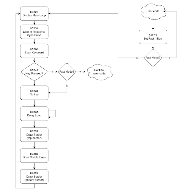
I will be glossing over lots of things here, but there is a rough description of what goes on in the code. If you want to follow along, check out Geoff Wearmouth's annotated disassembly (courtesy or archive.org)
$0229 - Display 1
This is called at the start of every loop
This checks if the PAUSE command has timed out and returns if it has
...on to...
$023E - Display 2
This calls $02BB to read the keyboard, the IO read triggers the vertical sync pulse
...back to..
$0241 - Display 2 Continued
This checks if a key was returned, and if we are in "fast" mode, returns to process it
...on to...
$0264 - No Key
That's right, no key was pressed
$026B - LoopB
This is a carefully timed delay and then the vertical sync pulse is ended
This then calls $0292 to display the top border
Then it calls $02B5 to generate the actual display
Then it calls $0292 again to display the bottom border
We then go back to $0229 to draw the next frame.
I have tried to draw that as a flowchart.
Drawing Routines
Looking in more detail at the two functions there, in the wrong order to make things clearer.
$02B5 - Draw Lines
This sets up the magic used by the ZX80/ZX81 of using the refresh counter to clock through RAM whilst the Z80 is executing NOP instructions.
To achieve that, it jumps into the display (yes, it executes the characters in the display). The hardware takes over at this point and feeds the Z80 NOP instructions until it hits a newline character which is conveniently (by clever design) the HALT instruction for the Z80. The hardware stands back at this point and actually lets the Z80 see the HALT instruction, so it halts and waits for the interrupt which comes at the end of the line. The interrupt handler then sets up the refresh counter for the next line and jumps back into the display.
When it gets to the end of the lines, it returns to the display routine.
$0292 - Draw Blank Lines
The is where the magic happens.
In "fast" it calls the above function, but points to the newline character at the start of the display file, so it will immediately stop and so a blank line will be drawwn. The interrupt handler then checks if enough blank lines have been drawn, and goes back around until the border is complete. It then returns back to the display routine
In "slow" mode, it enables the NMI generator so that an NMI will be generated at the end of the line, it then goes back to the user code and that runs until the end of the line. The NMI handler also checks to see if the border is complete, and keeps going back to the user code until the border is complete when it also returns to the display routine.

Stacks of trouble
There is an extra complication that took quite a while to get my head around, the way the stack is used. Some of these functions are jumped to, and some called as routines. In simple terms they are the same thing, but with one difference. JP just jumps to the code, but CALL pushes the return address onto the stack, and then jumps to the code.
The key thing comes in the way "slow" mode is handled. It is activated by a function at $0207 which tries to cause an NMI to see if it works (since the ZX81 ROM could also be run on the ZX80 which didn't have the NMI hardware and so could not activate "slow" mode)
When the user code calls $0207, it's return address is pushed onto the stack. If slow mode is enabled, the main register pairs are also pushed onto the stack, it does not return at this point, it jumps to the display code.
(when the display is running, the stack contains user code return address and registers)
Sometime later when we are drawing one of the borders, the function at $0292 pops the four main registers back off the stack and then returns to the user code.
When the NMI handler is called, the user code return address is pushed onto the stack, if it is still in the border, it returns to that address. If it is finished, it leaves the return address on the stack and then pushes on the four main register pairs again and back to the display file.
(the stack again contains user code return address and registers)
I have to admit it did take me a long time to get my head around they way the stack was used by these routines. It's also important to know the ZX81 ROM contains no RETI, RETN or DI instructions. It never officially returns from interrupts, or disables them. It relies on calls to the interrupt handler to disable interrupts, then jumps into other code.
How to replicate that without NMI
My turn to make changes now.
I am trying to make a few changes as possible to keep this compatible. On the ZX80 version, it was easier as that ROM was only 4K, and the Minstrel 4th ROM was 8K (+ 5K extra), so I could add new routines in the 4K space.
The first of those had to copy the ZX80 font from it's ROM into the read only character ROM on the Minstrel 4th. It remains writable, so us users could actually change the font if they wanted to. So far I have only found one program that tries to write to that area (which is normally a ROM mirror on the ZX81) and that is a system info program, so that fine.

I know from the ZX80 version that some games jump into various points of the display routine to do "flicker free" graphics and things like that, so I want to try to keep all the entry points I know about the same.
The system I am trying to replicate get an IRQ every line, and with the option to control the generation of an NMI every line as well.
The hardware I have to implement that on generates an IRQ every frame.
How hard can it be?......
.... two weeks later ....
After many, many attempts to get this working, and several "scratch that, go back and start over", I have come up with this.
$0292 - Draw blank lines
This now does nothing. It just returns
$02B5 - Draw display
This is important as it is the entry point for various games who have used their own code during the borders and just want the display bit drawn.
That is what I do, parse the display, reading the display file which may or may not be collapsed and generating the memory mapped display in the Minstrel 4th video RAM area.
Once complete, it does one of two things:
- In "fast" mode, it enable interrupts, and halts the Z80 until the interrupt at the start of the next frame.
- In "slow" mode, it does what $0292 used to do, it POPs the registers off the stack and returns to the user code.
The new IRQ handler is fired at the start of the next frame and again has two choices:
- In "fast" mode, it returns to the new display code, which returns to the old display code.
- In "slow" mode, it PUSHes the main registers onto the stack (which already contains the address of the users code) and heads off to the display code to scan the keyboard.

The section where the Minstrel 4th video RAM is being accessed is when the screen is being copied by the new display routine. You can see it takes almost as long as it takes to draw the actual frame (when the CRTC is addressing the same video RAM from the other side).

The section when it is not accessing the video RAM it is either halted ("fast" mode) or running user code ("slow" mode).
That works out to be about 6.5ms out of 20ms. About the same (well, a little more) than a ZX81.
If I jump ahead to things working, here is the result of a ZX81 speed test program.

When run on a Minstrel 3, it takes exactly as long as the stock ZX81 figure (good to know).
When run on the Minstrel 4th, it shows it is indeed faster, about 115% the speed of a ZX81. Makes it a little more responsive, but shouldn't cause too many issues for games etc.
(I later optimised the code further to get it almost twice as fast, but in the end decided to add a delay to get it to 100% of the speed of a ZX81 - I will cover the optimisation in a separate post)
Some colourful diagrams
Let's try and show that with some more colourful diagrams of a video frame in "fast" mode. Here green at the top shows when the keyboard is being scanned during the vertical sync pulse. Black shows where the screen is being drawn, and blue where the Z80 is halted.

When code is being run (red), it stops generating video frames or scanning the keyboard until the user code lets it restart.

In slow mode, you can see the borders at the top and bottom are now used for user code (red), with the visible lines in the centre as before a mix of drawing characters (black) and waiting for the start of the next line (blue).

In the Minstrel 4th version of "fast" mode, the keyboard is scanned (green), the screen is copied (black) and the rest of the frame is spent halted (blue), waiting for the start of the next frame.

In Minstrel 4th "slow" mode, the keyboard scan and screen draw happen as before, there is then a cycle counted delay, and then the user code is run (red) until the interrupt at the top of the next frame.

The delay (in blue) has been adjusted so the time the code is running (the red area) is the same as the ZX81 in "slow" mode.

RAM
The Minstrel 4th has lots of RAM, in various places.

The ZX81 as standard, only knows about RAM from $4000-$7FFF, I have left it like that, so it will appear as a 16K ZX81 for best compatibility.

The system variable RAMTOP is stored at 16388 and 16389, reading that shows the address of the first byte that is not being used by BASIC.

32768 shows the RAM runs from $4000 to $7FFF as expected.
You can use the standard procedure of POKEing RAMTOP if you want to enable the full 48K of RAM.
There is an extra 1K from $3C00 to $3FFF that you could use, and the "scratch RAM" at the top of video RAM from $2701-$27FF is also available (but not $2700, that needs to be set to 0.
Other Changes
I also had to make changes to the load, save and keyboard scan routines to cope with the hardware changes.
As with the ZX80 version, the display remains active during load, so I have added a countdown.

This shows the number of bytes remaining (in hexadecimal). This is based on a value read from the start of the program. If that is wrong, the countdown will be wrong. If you ever see over $4000, then it is probably corrupted and you may as well rewind and start again.
Limitations
Most things are working. 3D Monster Maze was my test, that needs "slow" mode to work, so wouldn't work on a ZX80 with the 8K ROM (or a Minstrel 2). Pleased to say that works fine.

I also wanted to test Paul Farrow's Kong and PacMan, as those use flicker free code for ZX80 compatibility, those also work.

Anything which uses a pseudo-high-resolution graphics mode is not going to work. Because of the display setup, only pure character based displays will work. So no Rocket Man or 25th anniversary demo I'm afraid.
Anything which uses a fancy tape loader will fail as that will be reading the wrong pin.
Anything which uses it's own keyboard scanner will sort of work, with only the middle 8 keys on the bottom row reading incorrectly. If you press X, it will see that as Z. Anything which uses the standard INKEY$ routine or LAST_KEY etc. will be fine.
For example, Mazogs uses it's own routines, so instead of V for view, you have to press C.

The problem is due to the Symbol Shift key being physically located between Shift and Z, but logically being to the left of Space.

When I designed a membrane overlay for the Minstrel 4th for a standard ZX81 membrane, I had to put they keys where they logically were, leaving the characters shifted to the right.

The only thing I have found so far that does not work is Dave Stephenson's Tut-Tut. I am not sure why, the later Minoss Knossoss works OK.

It starts up, display part of the title and then fulls the screen with garbage and gives up (update - I have now fixed my display code so that Tut-Tut can run unmodified - http://blog.tynemouthsoftware.co.uk/2025/06/a-zx81-game-on-a-zx81-emulator-on-a-jupiter-ace-emulator.html)

Further investigation seems to point at a Z88DK, the compiler used. That has it's own display routine which for some reason transposes IX and IY compared to the original. I can't easily see a way of making that work, it may be possible to build it without that version but I couldn't get Z88DK to build from its source (or indeed get Tut-Tut to build from its source when I used a pre-complied binary of Z88DK, so at that point I gave up)

Fear not there is a port of Tut-Tut for the Ace by George Beckett, so you can still run that version (George has also written a version of 3D Monster Maze, so now you have a choice).
Future features
This is still considered experimental. It works well enough for 10 PRINT "HELLO" 20 GOTO 10 and all of the programs that I have tried (apart from the ones with high resolution graphics that I expected to fail and Tut-Tut which I didn't expect to fail).
I figured the chances of anyone having a ZX Printer and bothering to find a way to wire it up to the RC2014 bus is low, so I think the three ZX Printer commands are up for grabs.
In future I would like to replace the LLIST and LPRINT commands with version of IN and OUT. These would work as on the Jupiter Ace and the ZX Spectrum, OUT 1, 255 would be write the value 255 to port 1, and LET X = IN 2 would set X to the value read from port 2.
I did try to do that, and OUT was OK, but IN is going to take a bit more work as it is going to need lots of things shuffled around to add it into the operator precedence list.
I would also like to add a BEEP command to make use of the Minstrel 4th's speaker. That is also going to require a bit of thought, so I have left those out.
Adverts
Your reward for reading all of that is notice that there is 15% of everything in my Tindie store throughout July.

The Minstrel 4th (with the updated ROM including ZX81 BASIC) is available as a kit or built and tested, from my Tindie store.

It is now also available from Z80kits.com, home of the RC2014.

There you can get a bundle with the Minstrel 4th, RC2014 backplane and whatever modules you wan to go with it.

Patreon
You can support me via Patreon, and get access to advance previews of development logs on new projects and behind the scenes updates. New releases like this will be notified to Patreon first, if you want to be sure to get the latest things. This also includes access to my Patreon only Discord server for even more regular updates.


