As promised (admittedly a while ago), here is the first of the development logs covering the early stages of Mini VIC development, this from Patreon January 2022.
I have been trying out some options for a potential Mini VIC, a VIC20 compatible computer made with modern parts - and specifically without using a VIC chip.

The board I made last year (January 2021) was almost that. The idea was to use the same form factor as the VIC20 CR, so it could be used as a drop in replacement.

I used all modern parts, with the sole exception of the VIC chip. I used an original chip so that I could test out everything else before moving onto the big challenge of replacing the VIC chip.
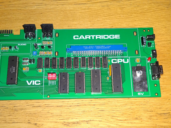
At the time, I looked at various options for replacing the VIC, but got bogged down in dealing with the bus timing and colour generation, and left it for a while.

I recently saw a video of a "Commodore 64 on an Arudino".
https://www.youtube.com/watch?v=jMNXyMuxqfE
This was quite impressive in that it did both 6502 emulation and video generation within the ATmega328P of an Arduino Nano, albeit with black and white text only BASIC and 1K of RAM available.
That seemed an interesting thing to investigate, so I had a go at recreating it.

I did get a picture, but my LCD wasn't happy with it, it was faint and flickering.

To help the signal, I added a transistor buffer, the same as the output stage I use on the Minstrel and Mini PETs.

With that, my LCD monitor was happier with the signal and chose to display it.

Ignore the blue tint, that's just the camera. The signal is black and white, with a white border, white text, and a black background. If anything, easier to read than the lilac and purple of the original C64.

That was interesting, and shows potential. I had a bit of a look around at how that was working.
One thing I noticed was the font data was not as expected. The Commodore font ROMs are arranged as 8 bytes per character, with each byte being the bit pattern for one of the 8 lines.
To borrow a frame from that video, this is the pattern for character 0x00, the @ sign.

That matches the start of the VIC20 font ROM:

The C64 font ROM was redesigned so that no lines were 1 pixel wide, as this can cause strobing on some TVs. This wasn't an issue on the PET (with it's built in green screen monitor), or the VIC20 (with it huge characters).
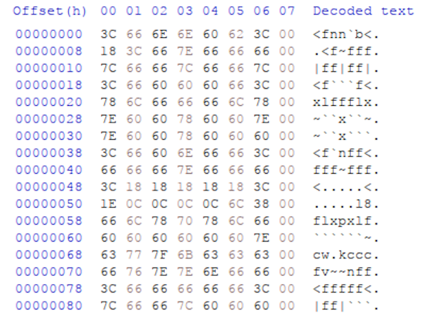
So, in theory, the C64 font in the Arduino code should start 0x3C, 0x66, 0x6E, 0x6E etc.

But it doesn't. The 3C is correct, but not the rest. It turns out that the 66 is actually located 256 bytes away, and the 6E 256 bytes after that and so on. The array has been rearranged quite cleverly to reduce the number of instructions required to read it.
Rather than charROM[256][8] as would match the original ROM, it has been arranged as charROM[8][256]. That might not seem much of a difference, but the 8 bit AVR accesses the data using two bytes of the Z register, and in that arrangement, the lower byte is just the character code, and the upper byte selects 1 of 8 block of 256 bytes, each representing one line of each of the 256 characters.
UDR0 = pgm_read_byte_near(&charROM[line & 0x07][*(p_vidmem++)]);
or, load the USART data register with a byte read from program RAM, from an address in the charROM array indexed by the line number (masked to the range 0-7 for 8 lines) and the character code read from the video memory.
That's quite a line, and amounts to about a dozen lines of assembler. Swapping the indexes around generates too much code to fit within the 16 cycles between each character (40 characters = 8MHz dot clock = 16 cycles at 16MHz clock).
I know this is early days, but I know the thing I want to write will have to work with an unmodified character set as this can be set as ROM or a user character set in RAM. I figured with some hand optimised assembler I could fit it in.
The "C64 in an Ardunino" code is written in C, and exhibits some of the timing issues I worked hard to avoid on the Mini PET. A disadvantage of doing timing critical things like that in C is the changes in the libraries or the compiler can cause your code to stop working, as can be seen with the original project from about 10 years ago which now does not work. I would guess that if you were to dig out the Arduino environment from about 10 years ago and rebuild the code, it would generate assembler which did fit the timings (or maybe it never did?)

The aim has to be to get those vertical line straight. The wobble is caused by interrupts not always happening on exactly the right clock cycle. If it is in the middle of a multicycle instruction, it will wait until that is complete. It is the sort of problem that the optimising C compiler can ruin your day with.
Code that was working and producing a sharp vertical line can turn to something wibbly when you move some unrelated code around. Some instructions that take either 2 or 3 cycles depending on whether they cross a page boundary and things like that can alter the timing enough to mess up the display.
For the Mini PET, I ended it writing it all in assembler so I had full control over that. A key tip for this sort of thing is to put the processor to sleep before an interrupt is expected, then it will always interrupt at the same cycle.
I did some testing messing around with changes to this code to try to do that, but I knew I was going to rewrite it anyway.

I experimented with adding a border and inverting the bitmap to give a closer look to the VIC20. The jailbars were unintentional and caused by using the XCK pin, which gets used a clock output in USART in SPI mode.
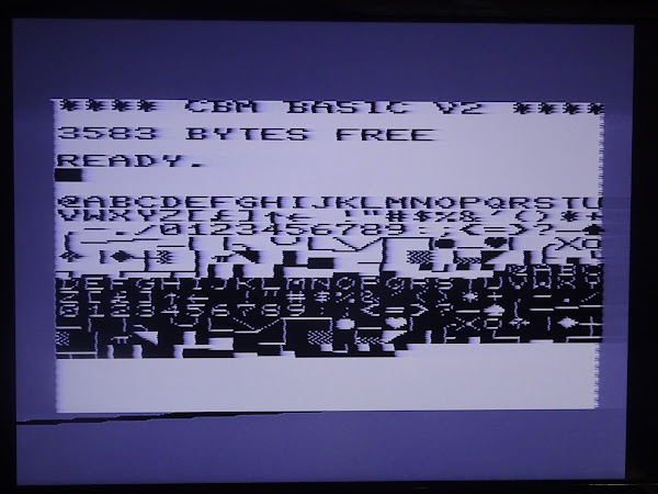
I then broke something and the timing went out again, but I had enough of a proof of principle to move onto the next phase and write my own version.
The important thing I took away from that code was using the USART in SPI mode to generate the pixels. I had not previously considered this. I had looked at using the USART in normal mode and also at using the SPI circuitry, and neither could be convinced to spit out a stream of pixels like a shift register would. However, it seems the USART can be made to do that when it is a set in SPI mode.
I had added a 74LS07 buffer to the signals so I could monitor them. The C64 code was using some of those pins in open drain mode (writing 0 to the PORT register and then turning that on or off using DDR). That made it difficult to probe those signals as they were not being pulled up separately.

I started off with my Mini PET CRTC code and ripped out all of the alternate timings used by the various PET and RGBi monitors and left just composite video and ran that up using the Arduino hardware (since it was already setup).
The Mini PET CRTC was only designed to do the timing, and control of external video RAM, font ROM and a shift register, so there was no pixel data generation. For the first testing, I just setup alternating black and white characters.

OK good start. Not quite got the timing of the border signal right, it's wrong in various ways in most of the rest of the pictures, but I finally fixed it near the end.

So far, so good. This was doing the video RAM lookup, and outputting the character code on each of the 8 lines. Seems to be doing the right things.
Next was the font lookup.

Hmm, OK, that's something, but it's not right. I added the character table to show all 256 characters and looking at that, I think I know where I went wrong.

The second half is wrong. Ah. I see. When setting up the array address, you have to multiply it by two, as the address of the array is in two bytes words. I had also multiplied the character code. It's a shame because than meant it was split neatly into two nybbles.
I was able to use the swap instruction to exchange the nybbles, and then mask off 0x0F and 0xF0 and add to the two halves of the address register.
To test the theory, I removed the left shift which multiplied the line number by 2 and tried it.

Ah, that's better, so it is working, but the character code is being unnecessarily doubled. That appeared to make the maths more complicated, but in the end I was able to do it in a few instructions using multiply. I normally don't consider using multiply in assembly code is it is not available on the 6502 and slow on the Z80, but on the AVR it is only two cycles.

That a lot better. Just need to invert the characters to better match the usual colour scheme.

Next get rid of the extra lines (it is still showing 25 lines as it was based on the PET code) and finally fix the border position.
As part of the final tidy up I got rid of the 74LS07 buffer and changed the value of the border resistor to make it a lighter grey. That also cleared up a bit of streaking in the image. I had removed the blanking signal used in the original (as that could be provided by the pixel data pin), and added the border, so it was a similar number of parts (+ the buffer transistor and 75 ohm resistors).

But it's not a bad black and white version of the real VIC20 (although the colour scheme looks more like a C16, more on that in another post......).

The colours are going to be tricky though to get the above screen looking like a real VIC20 (or here, one in an emulator).

There's still quite a big list of things to do.
Read from RAM - This test code has hard coded font ROM and video RAM. The final version will need to read out of the VIC20 RAM, this has to be within the 16 cycles available per character and also in the half of the 1MHz clock cycle when the 6502 isn't accessing RAM. Since the CPU clock is generated by the VIC chip, that can be controlled, and maybe I could look at an asymmetric clock like the C16 has to allow more time for the video RAM access? This is going to need a bigger microcontroller, which is a little tricky these days as they are all out of stock. Time to dig out some old development boards and see what I can use. I am trying to stick with 8 bit AVR chips as that is where I am most familiar. I could just use a bit ARM chip, but at that point you may as well just use a Raspberry Pi and run an emulator.
Colour - I have been looking at generating RGB outputs on another project, but the VIC 20 has an unusual selection of colours, rather than the usual red, green, blue, cyan, magenta, yellow etc. Those also vary a bit between PAL and NTSC machines
I am not sure how I am going to generate those yet. It is probably going to have to be analogue RGB rather than digital.
Register control - Monitor and respond to write to 9000-900F to change settings and support all the different screen size and character size options.
Sound - The VIC also generates sound with three voices and one channel of noise. I think I will probably farm that off to a separate microcontroller as there will not be enough available timers in the main chip
Analogue input - The pot x and pot y from paddles are read via the VIC. Should but easy enough with the ADC in one of the microcontrollers.
All in all, quite a lot of work to do, and lots of points where it could fail. There is also the point that it will probably never be 100% accurate, so some of the bleeding edge demos might not work. I think I will be happy if it passes my VIC20 Dead Test, and can run Cheese and Onion from a Penultimate Cartridge.
But that is a long way away.
Advertisements
Minstrel 4D
No Mini VIC kits any time soon, but the Minstrel 4D kits are shipping now, you can order one from The Future Was 8 bit - SPECIAL OFFER - £15 off the Minstrel 4D and free shipping to the USA
https://www.thefuturewas8bit.com/minstrel4d.html
Now includes the option to have your kit hand built for you by one of the many specially trained kit assembly technicians at TFW8b. Who am I kidding? It'll be me, won't it.
More info in a previous post:
http://blog.tynemouthsoftware.co.uk/2022/08/minstrel-4d-overview.html

Patreon
You can support me via Patreon, and get access to advance previews of posts like this and behind the scenes updates. These are often in more detail than I can fit in here, and some of these posts contain bits from several Patreon posts. This also includes access to my Patreon only Discord server for even more regular updates.
https://www.patreon.com/tynemouthsoftware