Wednesday, 8 February 2012

Samsung LCD TV's - power supply fault

This is an old post, preserved for reference.
The products and services mentioned within are no longer available.

My parent's bought a Samsung LE40R74 the same as mine, because I'd been into Curry's and peered through the grill on the back and seen that inside was the LTA400WT-L01 panel. At the time I worked with large LCD panels as part of public information displays (bus stations, airports etc.), and that was one of the panels we had chosen to use, so I knew the were fairly decent and had seemed to stand the test of time.
They got it and it did the job very well. Then it went off, or rather it started occasionally switching off, and sometimes wouldn't switch on. So I took the back off and had a look around, and there seemed to be a couple of dried up capacitors which had opened their vents. Capacitors work the opposite way around to mussels, if you cook them and they open up, you throw them away. I noticed that the ones that had gone were very close to a heatsink. It seemed to be a poor design, that close to a heat source, they are bound to dry up over
The duff capacitors were filters on the low voltage and standby side of the power board, so presumably as they had dried out their capacitance reduced and so it was failing to generate sufficient power to keep the TV on.
I popped out to my wonderful local electronics shop (ESR) and got some replacement caps, 105C rated and replaced all those in the area around the heatsink and away we go, the TV is back up and running.
That was a couple of years ago, but since then a couple of people have come to me with similar Samsung TV's with similar symptoms. I don't normally repair TV's, but in this case, it sounded like it was the same issue. And indeed it was, these ones also had dried up capacitors, in the same place around that heatsink. The later models seemed to have gone for 2200uF rather than 1000uF, and yesterday, another one arrived, an LE40R88, same problem, but in this one they had used 25v caps rather than 10v as before, which was still sufficient for the 5v rail. So it sounds like they are trying to fix this problem by changing the caps, but they seem to have moved them closer to the heatsink!

Thursday, 2 February 2012

Universal Laptop Power Supply Further Update

This is an old post, preserved for reference.
The products and services mentioned within are no longer available.

After using this for a while, I've made a few changes. The power LED was wired in place of the original on the unit and wasn't ideal. As there is a delay in starting, it doesn't light immediately, and if there isn't much load it doesn't go off immediately. The combined with a possibly dodgy mains switch led me to make a change. I also thought a couple of 4mm posts would actually be a good idea, to make the unit more general purpose, so time for a bit of rework.

I added the 4mm posts and a new 'output on' LED wired across those (well almost +V is taken from the input side of the ammeter so as not to show up on there. I also removed the original 10K divider resistor from the main PCB and replaced it with one directly on the output, to remove any voltage drop from the internal wiring and the ammeter.
I replaced the faulty mains switch with a chunkier one and added a mains LED. I replaced the mains socket on the PCB with a 0.156" header to tidy up the wiring.

And now here is the finished unit, next to my existing 5V / 12V bench supply.


Note from 2022: This is still in regular use, still with the "temporary" pencil labelling.

Thursday, 26 January 2012

Universal Laptop Power Supply Update

This is an old post, preserved for reference.
The products and services mentioned within are no longer available.

I've been looking further at this unit and have decided to rehouse it in a bench power supply case and add some additional features.

One useful thing in a supply like this, particularly when testing laptops, is an ammeter. This will show if a laptop is charging, and indeed how much it is drawing from the supply. I've also been looking at the voltage selection and the low voltage feedback side of the supply. It uses a potential divider across the output, 10K at the top and the bottom is one of a selection of precision resistors, chosen by the position of the switch,  ranging from 1240R to 1910R. The centre of the divider is used to drive the LED on the opto isolator back to the mains side.

I've been doing the maths, and it looks like it needs to be about 2.6V to switch on the LED, which will switch off the chopper driver. So, when the output voltage is high enough to make the voltage at the divider is over 2.6V, the LED turns on and the chopper stops charging the output capacitors and the voltage drops until it is below 2.6V, the LED turns off and the chopper starts charging the output capacitors again.

The original selector switch is 11 position, and the lower 4 have an additional signal diode in series with the resistor. This seems to be needed to keep the overall resistance in the same range, by knocking 0.6V off the LED voltage.

In rehousing it, I did think about removing the existing switch and wiring a replacement from the front panel, but I thought I could probably just replace it. I did a bit more maths to work out the best replacement resistor values, and could make reasonably close to most of them with a combination of 2 standard E24 1% resistors. In the end, I thought if a job is worth doing, do it properly, so I went for a 12 way switch with 12 500R multiturn pots and approximate values to set the desired values mid range in the pots. I used multi turn pots for the best accuracy, and ended up with about +/- 1V adjustment on each one which has left me lots of room to set them as accurately as possible.


I thought I may as well use the extra position on the 12 way switch, so I added a 24V range, I also changed two of the lower ranges from 14V and 15V to 13.8V and 14.4V as these seemed more generally useful.

I would normally use 4mm terminals for something like this, but I wanted to keep the original cable, which is a single piece of coax, so I went for a 3 pin XLR connector for the output, more than sufficient for the maximum rated current.


So here is the finished unit, temporary labelled in pencil.


Note from 2022: I am still using this regularly and the front panel is still labelled in pencil.

Friday, 20 January 2012

Universal Laptop Power Supply Teardown

This is an old post, preserved for reference.
The products and services mentioned within are no longer available.

I've been using a 'Universal Laptop Power Supply' for the last year or so to test laptops where either the owner hasn't brought the charger or there is potentially a problem with theirs. It seems to do the job, it's a 120W unit with selectable voltages from 14V to 22V, and a selection of tips that have suited every laptop I've used it with, except for one old Dell laptop.

Recently though it's been making a buzzing noise under load. Not necessarily a problem, but it's been getting louder and more annoying. So, I thought it was time to take it to bits and see what makes it tick (or rather buzz).

It seems to be fairly well made compared to some units I've seen. There is some unpopulated area at one end, which appears to be a 5V USB charging supply option not on this model.

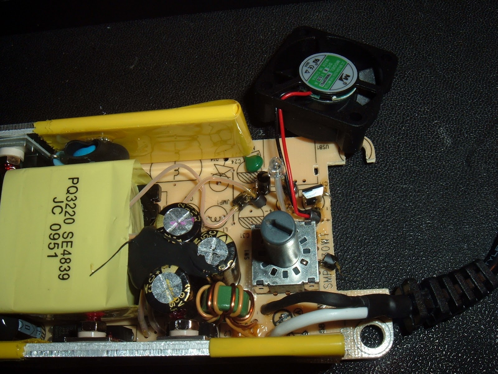
Turns out the fan on there was making the noise, an 8V 30mm unit. I've removed it and tested it on a bench power supply, at 8V and it runs fine, as noisy as expected from a small fan, but not as bad as it had been inside the PSU. It seems it was being driven by a voltage which slowly rises with load, and at about 3-4V it is trying to start but fails to spin and just sits there and buzzes. Not a very good design really, it shouldn't be run below a safe guaranteed starting voltage, in this case, about 5V.

UPDATE: Comments disabled on this post as it seems to attract a lot of spam.

Wednesday, 30 November 2011

Hotswap IDE bays

This is an old post, preserved for reference.
The products and services mentioned within are no longer available.

One of the things I need to do a lot with building and repairing computers is to remove a hard drive and attach it to a second system to do an offline virus scan or attempt to recover data. For SATA drives that is easy, I have a couple of eSATA docks which allow me to slide in any SATA drive without a problem. As SATA hotswapping is not a problem (at least with AHCI mode in the BIOS), this allow me to boot the known working system and get the virus scanner an everything up and running before attaching the drive. Hopefully this should detect any bootblock issues etc.

I still have need to test IDE drives, and they are more of an issue as I either have to dismantle the second PC and connect it internally, which means it is present during boot which isn't ideal, or I have to mess around with USB-IDE adapters and external power supplies which isn't ideal either as it is a bit of a faff and is limited by USB speeds. I got a couple of removable IDE caddies which improved things as it made it easier to connect to the PC, but still meant I needed to have the drive present during booting.
So the idea I had was to use a couple of IDE-SATA convertors. These little boards allows you to use SATA drives with an IDE host or, as in this case, use IDE drives with a SATA host. I did some testing with the drives powered up all the time, and connected via the adapters to the SATA ports on the motherboard and they were detected fine and accessible at full speed. All that was needed now was hotswap capability.
The caddies have a key operated power switch, which cuts power to the drives to allow removal. The SATA-IDE adapters only need 5V (usually provided by a 3.5" floppy power connector), so I found the switched 5V line on the back of the caddy and wired it to the SATA-IDE adapter power so it would be switched on and off with the drive.
Now for the test. Power it on before boot to check it all still works, yes, no problem. So now I booted with the key turned off, and once booted, turned they key on. The drive spun up and was detected just as if I had slid in a SATA drive. I then made a second to complete the pair and now use these regularly for testing IDE drives.

For Data Recovery or Virus problems, see www.tynemouthsoftware.co.uk

Wednesday, 9 November 2011

Home Theatre PC

This is an old post, preserved for reference.
The products and services mentioned within are no longer available.

I have an existing HTPC that does fairly well with an Asus board with an Atom / Ion, and handles full HD acceptably well thanks to VDPAU support in MythTV. I now need another one, so I've been looking around at the options. The Atom / Ion boards are still there, as are the AMD Turion's as so on.

In looking around I found a few fairly reasonable Sandybrdige boards with the H61 chipset. This seems to be a cost reduced version of the H67, and is missing a couple of PCI Express lanes and SATA 6GB/s ports. So I looked at the 1155 process options and the until the Sandybridge Celerons are released, the Pentiums seemed to fit the bill, again fairly reasonably priced compared to the i3 series, but with a few features missing. The important ones like the onchip Intel HD graphics and the memory controller which gives Sandybridge such high memory bandwidth.

So I went for an Asrock H61M-ITX board and an Pentium G620 for just over £100, add 4GB of DDR3 memory and that took it to £120, which I think is less that the Atom board cost a couple of years ago. Performance wise I was very impressed, with better memory bandwidth scores than my i7 950!

I went for the same case as the previous one, a cheap unbranded ITX case with a 250W PSU. I quickly decided to make the same modifications to the case as with the previous one, namely getting rid of the two noisy fans. There is an 80mm fan on the front and a thin 80mm fan in the PSU.
The heatsink on the G620 gives a fair indication of the amount of heat likely to be generated, so I don't think they are both necessary. As the PSU fan is the 10mm thick variety I didn't want to replace it with the same type, so I used a normal 80mm fan outside of the PSU case, using the original mounting holes, but from the other side. The three pin fan header could then be connected as a chassis fan and speed controlled by the mainboard BIOS.
I also took the opportunity to remove the 3.5" hard drive cage as I was using a 2.5" SSD. Since the front fan was no longer present, I bolted the 2.5" SSD in its place, and also attached a couple of internal USB ports in front for the wireless keyboard / mouse receiver. It isn't the best, but putting it behind a big metal box doesn't help, so out in front, there is only plastic and air between it and the keyboard.
After a painless install of Mythbuntu 11.10, it found my myth backend and I was watching HD TV again in no time.

Friday, 10 September 2010

Hard drive recovery


This is an old post, preserved for reference.
The products and services mentioned within are no longer available.

I've been having a lot of problems trying to recover a laptop with a damaged harddrive. The drive has had it, increasing bad sectors and clicking noises, but I am trying to recover what I can.

Most of the utilities I would normally use can't help here, either they give up when they reach bad sectors, or the can't work if the NTFS file system isn't clean. Ghost stopped on the bad sectors, even with the command line switches set to ignore them. So down to Ubuntu and linux tools.

ntfsclone is usually very good at this sort of thing, but kept saying I needed to start windows, run chkdks and reboot twice before continuing. And after several chkdsk's with repair and scan for bad sectors and many reboots still no success.

I finally got a good result using myrescue, a version of dd which was tolerant of bad sectors. It has a clever feature which skips a number of sectors after it finds a bad one and continues to read all the good ones before going back to the ones around the bad areas.

I used this to make a clone of the damaged drive, and was then able to successfully repair the filing system on the copied drive.