Friday, 18 July 2014

Commodore 64 PLA replacement - Mark II

This is an old post, preserved for reference.
The products and services mentioned within are no longer available.

I previously looked for a replacement for the Commodore 64 PLA, and tried an EPROM based solution. This sort of worked, but only on some systems, and was basically limited due to timing issues.
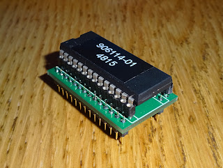
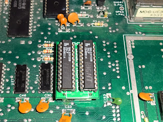
The PLA basically has 16 inputs (17 including CE) and 8 outputs. Replacing those is tricky as there aren't suitable chips of that size available. The solution I have come up with is to use two chips with 17 inputs and 4 outputs each, giving the required number of pins. They can sit either side of the rows of pins in what used to be called a butterfly adapter.

The chips I have used are GAL22V10s, these have 22 I/O pins, 10 of which can be outputs. That seems to add up, and leaves one spare pin. I have connected that between the two devices as it may be required for timing reasons.


The equations are available on the nets, and described in fantastic detail in the article The C64 PLA Dissected. I've split the connections according to the easiest wiring and in a combination of optimism and laziness, went straight to PCB. It's a small board, 1" x 1.5", so doesn't interfere with the surrounding components.

One of the reasons the EPROM based solutions have problems is timing, mainly around the CASRAM signal. This should be activated slightly later than the others, to avoid conflicts. It's basically a catch all, if none of the other devices, are activated, access the RAM. To achieve a slightly longer propagation delay, I've generated the signal on the left chip and passed it through to the right chip which passes it to the C64 board (when the chip enable is active anyway). This double delay seems to do the job nicely.
I have some spare boards, so contact me if you would like a PCB or a completed module.

2022 Update: The timing required seems to vary from board to board. These sort of worked, but not universally, same as the EPROM version.

6502 ROM / RAM Replacement

When fixing old computers, a frequent problem is 'black screen', where the computer appears to be powered on, but nothing appears on the screen. Many things can cause this, failure of the CPU, ROM, RAM or the glue logic in between, or the video out or other peripheral items. It's often a process of elimination, starting by removing unnecessary items, and swapping out the socketed chips one by one.
Various things can help with this, diagnostic cartridges like these run their own code either without needing RAM (or sometimes have their own RAM), and can identify various type of problems. But these are not always an option, in computers which don't have cartridge slots for a start. In trying to diagnose some issues with a Commodore Pet, I looked around at various solutions to this, such as bitfixer's Pet Vet, and Nicolas Welte's Universal 6502 RAM/ROM Expansion. Both essentially do the same thing, they plug into the 6502 CPU socket, and selectively isolate the CPU from the rest of the system. They can be configured so that any ROM access uses the copies of the system ROMs (or even different ROMs) on the expansion board, rather than the ones on the main board which may be faulty. It does the same from RAM access, it can use RAM on the expansion board to replace and/or expand the main board RAM.
The universal RAM / ROM expansion has some RAM and ROM and uses a gate array as glue logic, and dip switches to select options. The Pet Vet is a slightly more complicated solution, in that it has RAM over the entire address range, and a microcontroller. At power on, the microcontroller writes the contents of ROM images into the RAM and loads a truth table into a smaller RAM to work as address decoding glue logic. It also has a serial interface to control things.
I like the idea of the simpler unit, and tried a few times to contact the author of the universal ROM RAM board to buy a board or a kit, but didn't get any response. I'm not sure if the page is still active, since the news page was last updated in 2007. There are however, Eagle PCB files and JEDEC files for the GALs, so I thought I'd build my own. The page describes a later mod to add a jumper for 15xx disk drive memory maps, but the PCB files are an older version. I converted the Eagle files to Diptrace, added this jumper and made a few changes to the routing (force of habit, I like neat traces).
The layout is quite tight, with the CPU pass through inline with the CPU socket, and two TTL chips live under the larger sockets. Testing was as described on the site, the usual visual inspection, and then deep intake of breath turning it on for the first time.
The first test was with no ROM or RAM, and a jumper wire to replace the GAL and set the 245 to just pass through to the main board. Obviously, testing at this stage is best with an already working computer, in this case a VIC 20 CR.
So far so good, so time to install the GAL, a small programmable logic device with 16 inputs, 8 of which can be outputs (GAL16V8). This replaces a pile of TTL chips, and also allows the logic to be changed for different memory maps.With all the DIP switches off, this should also pass through.
Add ROM, and the system ROMs can be replaced, add RAM and the system can be selectively expanded.
Here is the VIC20 with the system ROM replaced and a full 32K of RAM (of which 28159 bytes are available).
It stands off the board via an extra DIP socket added to the bottom, but that isn't enough for the original version of the VIC 20 with the big heatsink and plethora of 2114 SRAMs. It needs another socket in the stack.
Here I've found yet another use for plastic business cards (I grabbed a pile when some people were leaving a company I was working for). They are useful for paint scraping, label removing, opening plastic tab cases, and now insulating 6502 ROM / RAM replacement boards in VIC 20s. This VIC 20 was showing a black screen. Rather than swapping out all the chips one by one, I was able to confirm it was the ROM chip by just removing the CPU and installing this board. A spare ROM chip later and it was up and running again.
Option ROMs can also be included in the image, and separately enabled. The board has space for a 1Mbit EPROM, so that would be 4 system ROM images and 4 option ROMs. In this case, I've just used a 27C256 with a fixed image of the standard PAL ROM images, and a VIC20 diagnostic tool in the option ROM slot. The original page talks about software to load ROM images into EEPROM using the VIC20, but I haven't looked into that as the downloads appear to be missing.
One thing to note, some of the RAM inside the VIC20 is used by the VIC chip to build the display, so the RAM on this board does not replace that. I've tried on a board where I've had to replace all the SRAM, so it is socketed. It appears to work with at minimum the left hand 6116 for screen RAM and the right hand 2114 as Colour RAM. It does mean you could remove the other RAM (particularly if it's faulty), and the original ROMs and reduce the power consumption.
Now that's built and tested, I'll need to modify the GAL code to fit the PET 8032 memory map and I can get on with testing that. I'll also have a go at a BBC micro version, should be good for that. I may do another spin of the board with a power LED and a reset button, but I still have a number of these boards available, so if you want a board or a complete unit and can't get in touch with the original author, contact me.

UPDATE # 1
This has now been used successfully to assist with my Commodore Pet 4032 restoration.

UPDATE # 2:
The new V2.0 6502 ROM/RAM boards are available now.

UPDATE #3
The new V3.1 ROM/RAM boards are available now

UPDATE #4
New smaller PET ROM/RAM boards are available now, specifically to repair/upgrade Commodore PET machines.

UPDATE #5

These current updated version of the boards are available to buy from my Tindie Store

Wednesday, 16 July 2014

Raspberry Pi Model B+

This is an old post, preserved for reference.
The products and services mentioned within are no longer available.

Dear Raspberry Pi Foundation, thank you for making my life a little easier.
The new release of the Raspberry Pi, the Model B+, has a number of improvements over the previous Model B, which should make life easier for those integrating the Pi, as I do with my USB Keyboards.
So what's inside the box? Well, a slightly smaller Pi. The main connectors are now on just two sides, rather than all four sides as it used to be. The USB jacks are now inline with the edge of the board, and there are now two of them, giving 4 USB ports. Theese ports are also now inline with the RJ45 magjack for the LAN. The network activity indicators are now built in, and the power and disk activity now moved to the other edge.
You can see the evolution from the original release of the Pi on the left, through the first revision which had two mounting holes added, to the new board, with four mounting holes at the corners. There are also more pins on the GPIO, it's now 40 pin, so time to dig out all those IDE cables which were also 40 pin.
The audio has been improved, and the audio and composite video have been combined into a single 4 pole 3.5mm jack. Power consumption should also be improved by use of switch mode regulators rather than linear as in the previous models. On the back, the SD card has been replaced with a micro SD socket.
Again, this overhangs less than the previous SD card slot, and should be more reliable. All these changes of course mean it will no longer fit in most of the current cases. They say old model B will remain on sale, probably until all the case manufacturers have sold their remaining stock of old style cases. Look out for some offers soon.
Here it is with its the namesake, the BBC Model B+, the last revision of the BBC Micro in the original case (the next was the wider BBC Master). 30 years later, this new B+ is 512MB, only 4000 times more memory than the B+ 128K.
I'll be using one of these in the next casemod (the Pi, not the BBC), so it will be interesting to see how much better it fairs.
In previous builds, it has sometimes been necessary to remove some or all of the connectors in order to fit it in the case, hopefully I'll not have to do that next time.

Thursday, 5 June 2014

Unnecessary Complexity

This is an old post, preserved for reference.
The products and services mentioned within are no longer available.

My entry for the 'What Dave doesn't like about modern life' round on Room 101 would be Unnecessary Complexity. By that I mean that things seem to become more complex all the time, just because they can. The example I usually give is word processors. I remember writing my university dissertation on a BBC Micro, using Wordwise. That was fine, it did the job, all that was needed really.
Later onto a DOS PC running Protext, again, did the job, added a few whizzy features like fonts and bold / italic, although they were more a feature of the printer than the word processor itself. Later again Microsoft Word on Windows 95. WYSIWYG editor, so it looked lot fancier. More fonts, more effects. Today I'm using Office 2010 on Windows 7. Even more fonts, even more features and buttons I never press.

The final step is Office 365 on Windows 8, and I've seen a lot of people stare at that very confused, because they have somehow managed to overcomplicate it even more by trying to make it simple.

But at the end of the day, all these things basically do the same job, type in some text, modify it, save it and print it. And bring in all the new feature like autocorrecting words (you might not want autocorrecting), autocapitalising (how many times have you missed the 't' out of 'it' and gone back to find the I had been capitalised?). Lets' not mention the office paperclip.
Wordwise ran on the 2MHz BBC in 32K (well, more like 20K if you remove screen RAM etc.). Protext runs in 640K on the 8MHz PC. Word 6 runs in 32MB on the 200MHz PC. Office 2010 is running on a 16GB machine with a quad core 3.1GHz processor. But they are all doing basically the same job, and actually the old ones are sometimes easier to use.

I came across another example yesterday, when talking about approaches to averaging. When you have a limited resolution reading, you can improve it by taking a number of them and averaging the readings. I used this approach for the temperature sensor on the LCD Clocks.
A very efficient way, suggested by a friend, is written in assembler. Take the 8 bit readings and add repeatedly to a 16 bit register, and at the same time increment an 8 bit register. Every 256 readings, the 8 bit register overflows. When that happens, take the top byte of the 16 bit register. Then clear the register and start again. This is a very efficient way of taking 256 readings and dividing by 256.

A little less efficient is the way I do it in C code for the LCD clock is to create an array of 100 bytes, each reading, set an array entry, increment the index, if it's at the end, move it back to the start. Then go through the whole array, adding the values to a floating point number and dividing by the number of readings. Less efficient, but it achieves the same thing.

In a desktop application, I need to do a similar thing to average readings on a chart, but here I'm writing in C#, and using the .net framework linq library. I create a linked list of readings, each time I add a reading, I go through the list removing any entries over a particular age. Then use the built in averaging of the linked list to get the average. This is a lot less efficient in terms of memory and processing.
All three of those involved probably a dozen lines of code in their relative language, and they are achieving the same thing, but the amount of code generated and complexity is increasing each time. The assembler version uses a couple of registers and no memory. The C version uses 101 bytes, the C# version uses considerably more for a linked list of floats,  but the code, memory and processing requirements are a drop in the ocean on a modern PC. The new code has lots of inbuilt safety checks, the old code relied on the author getting it right.

I think that is why I like working with vintage computers and amplifiers and things like that because the beauty in simplicity is thrown into sharper focus against the complexity of their modern equivalents. Older amplifiers had several transistors, modern ones have several thousand. The BBC's 6502 had 3510 transistors, where as the i5 in here has about 2 billion.

Sunday, 25 May 2014

Improved Arduino Frequency Counter

This is an old post, preserved for reference.
The products and services mentioned within are no longer available.

I built a Simple Arduino Frequency Counter last year, and it's been quite a useful project. Over the time it's been in use, I've been tinkering with it to improve the display and accuracy. This started off with a simple display of the frequency in Hz. I modified the code slightly to add some commas to make it easier to read:
That's how it stayed for a while. I'm now building a signal generator, and I thought it would be good to include this on the front panel, so I tidied the layout further and added a display of the signal period (1 / frequency).
I had noticed it seemed to read a little low, so I revisited the code to improve performance. The original worked by setting up an internal counter to count pulses coming into one of the pins. It waited one second, then read the counter. The count was taken as the frequency, the display was updated and the counter reset. I've now gone for a different mechanism, an interrupt driven approach, similar to that in this forum post.

I've altered that slightly, and now what it does is enable an interrupt on change on a pin. When that is triggered, it stores the start time. It then changes the interrupt to go to a different routine, and when that is called, counts pulses and stores the time of the last pulse. It then waits one second again and calculates the frequency, based on the time between the first and last pulse, to improve accuracy. As per the follow up to that forum post, I've taken into account ignoring the initial isr call as this may happen if the pin is high when the interrupt is enabled. I've done this with a third isr, again trying to keep the code in there down. The new code can be downloaded here.
The circuit remains very simple, basically connect the input to pin 2 (interrupt 0), and connect an LCD display however is most convenient, and alter the setup call to the standard Liquid Crystal library as appropriate. On breadboard, I used the pins nearest the display.
When transferred to a circuit board, all that is required is the ATMega328P, 16MHz crystal and 22pF caps, some 100nF decoupling caps and a main 47uF cap. The 10K multiturn pot is LCD contrast, overkill for what is required, but it fits neatly with the layout.
Add connectors for power, signal and the LCD. I used two 6 pin connectors as the central 4 pins of the LCD are unused. Again, these are wired using the  nearest and most convenient pins. The R/W pin is optional as it is always pulled low, but again for convenience, I connected that to a pin on the boarded version. The 6 pin 'stackable' connectors are used for arduino shields, but are ideal here as the long pins can be bent to make contact with the ATmega328P, reducing the amount of wiring to very little, mainly point to point using component leads.
I programmed the ATmega328P using the Arudino IDE and 'upload with programmer' and my trusty USBTinyISP. Then just install the LCD module, a standard HDD44780 based 16X2 LCD (in this case white on blue for a change) and connect up an input.
There is no input protection here, as it is intended to be used where the input is coming from a TTL chip in the same piece of equipment, using the same power supply. If you plan to use this with an external input, some protection and buffering would be required. This is left as an exercise for the reader.

Monday, 28 April 2014

Plustron TVR5 TV

This is an old post, preserved for reference.
The products and services mentioned within are no longer available.

One of the problems with fixing old computers is dealing with the TV out. Most of the time, I used an LCD TV which has a variety of inputs, HDMI, VGA, SCART, components, composite, analogue and digital TV. This does a decent job with all but the analogue TV for older computers where it is sometimes a struggle to tune in, particularly having to use the remote to tune in. Most of the time, I use a composite video or RGB output which many of those computers provide. Here is a nice crisp clear colour video output from a rather poorly VIC20.
However, things like the ZX81 and the Spectrum there is no video out, only TV out. I normally have to open up and clip on a little booster circuit to the modulator to get a decent composite video out. The alternative was to keep an old style TV for testing, and indeed I do, but it takes up a lot of space on the bench, so I tend not to use it.
However, I've recently been given a solution to this, it having been lurking in someone's loft for many year.
This is a plustron TVR5, a combined UHF TV and VHF/MW/LW Radio.
The TV side of it is only 5", but that's fine for the sort of use it will be put to. The tuning is nice and easy with an old fashioned dial, so no problem finding the computers signal. Here's that VIC20 with some 2114's replaced.
Analogue TV has been turned off in the UK, so there is nothing else on the dial, but again, that's fine for me, the only signal I'm looking for is this one.
The other advantage of this set is the size, it fits neatly on top of my trusty old Hitachi V-665 scope.
Could't resist the compulsory 10 print "Hello World".....

Monday, 7 April 2014

Nissan Leaf Review - One Year On

This is an old post, preserved for reference.
The products and services mentioned within are no longer available.

12 months and 6,000 miles later, the leaf is still going strong. It's still a great car to drive and is still very practical. 

The car itself is great, it just works, and it is the way things are going. It’s sort of like the change from mechanical hard drives to solid state hard drives. Initially, SSD’s were faster and quieter, but were more expensive and had lower capacity and a few teething troubles, but now they are getting faster and cheaper and a very viable alternative to traditional hard drives. Yes, the mechanical drives are still cheaper and offer large capacity, but are still noisy, slow, higher power and vulnerable to shock. 

The electric car / SSD analogy does hit a lot of similar points, the early adopters pay more and get more limitations and need to tell the world about how good they are. There are still people who will prefer multi terrabyte mechanical drives or 3 litre petrol engines, but for general day to day use, you don’t really need either of them. There are also hybrids that try to offer the benefits of both solutions, but purists don’t like them. And like the combined VHS recorder and DVD player, may not be around for ever.

There are still a few annoyances, the dashboard instrumentation, at least as far as the battery charge meter, is still rubbish, and the website, although better that it has been, is still flaky. The range I am getting in practical terms, is about 70 miles driving around town, 50 miles if you include motorways. So given this, it is really important to know how much is left and frustrating that the information is not available. What you get is 12 bars. 12 bars lit is 100% charge, 1 bar means alarm bells flashing and get somewhere to plug in very soon. And that's it, not much details. It does also give an estimate of the mileage remaining. This is usually somewhat optimistic. It is based on your current useage, so if you are driving on country roads, it will be higher than on motorways, even if you're on a long downhill bit, it will be higher than an uphill bit. So unless all your journeys are on roads which remain identical, the estimates are usually way out.

As an example, I had one of my longer journeys, 29 miles each way. As I left home, I had 12 bars and the estimate was 105 miles. So that should be easy right? Well, as I go there, 29 miles later up the A1, driving slower that usual to improve the range, I was down to 6 bars and 45 miles estimated remaining. The tricky thing, is was that 7 just dropped to 6 which would mean there would be enough left, or was it 6 just about to drop to 5, which would mean I wouldn't make it home.

It’s a bit like having a digital watch and someone putting some tape over the last two digits, so rather than 10:30, all you can see if 10:##. If you depart on a journey and it says 10:## when you leave, and when you arrived it still shows 10:##. All you know is you have travelled for less than 1 hour. If, when you arrived, it read 11:##, then again, it’s you don’t have enough information to work out if you could make the same journey again before lunchtime. It may been 10:59 to 11:00 and have only taken one minute, or it could be been 10:00 to 11:59 and been nearly two hours, or anywhere in between. So yes, the instrumentation is a bit rubbish.

Pushing the limits of the range, I've managed 80 miles in one day, on one charge, and that's as much as I generally need to drive. To achieve that, I did need to drive a bit like a pensioner on a day trip, keeping to below 60 MPH, and I had to keep the air con off as the heater uses quite a bit of energy. When you drive in such a way, the dashboard slowly lights up segments of pine trees, and you accumulate theses over a journey. On that, I got three or four on the way there and another three on the way back!

These days I'm not commuting as much so it's fine, I just jump in the car and go. Press a button to open the car, press a button to start, then just press one pedal to go faster, one to slow down and turn the wheel. On the odd occasions I've driven other cars it amazes me how much effort is involved, using keys, having to constantly change gear to keep the revs in the small practical range of the engine and so on.

Living in a terraced property, it's not always easy to plug in and charge. Some of my neighbours are very considerate, some less so. These days, I just plug in when I visit my parents, so free lunch are a charge up at the same time, but at less that 1p pre mile, it's not that draining on the electric bill.

So with production having moved to Sunderland, and with more than 100,000 sold the Leaf is going from strength to strength.