This is the story of the divMMC Future, a version of the divMMC SD card disk drive solution for the ZX Spectrum, produced by
The Future Was 8 bit.
From the start, this had to be the best divMMC you could buy, had to be small and neat and work on as many Spectrums in the range as it could, ideally all of them. It had to be as good as the
SD2IEC Commodore disk drive. This was quite a tall order, I don't think any of us realised what we had taken on.

My first involvement with divIDE and divMMC boards came when one supplied with a ZX Spectrum that came in for repair many years ago. The Spectrum had been working, but it didn't recognise the divIDE (can't remember what type it was), then the Spectrum failed (flashing coloured squares), so I was asked to fix it, and test it with the divIDE. The repair of the Spectrum was straightforward (dodgy RAM and TR4, one of which most likely caused the other). When it was working again, it still didn't see the divIDE. I tested that with another Spectrum board and it turned out it did work. Google at the time came back with result basically along the lines of 'yes, they don't work with some Spectrums'. I now know why, but at the time, wasn't able to provide a solution. I had similar results when I borrowed a divMMC (another type, sorry, can't remember what that was either), the owner of which said it was 'intermittent', and he was right.
divMMC Future V1.0
Move forward to August 2016, and TFW8b had just started to produce my
VIC20 Penultimate Cartridge. They had built some prototypes of a new divMMC board, and asked me to do some testing. They had done an excellent job squeezing the circuit into the form factor that had been chosen.
The board I received had already gone through a few changes, but would go through quite a few more as time went by. The issue at the time, and the one that persisted through many versions was that of compatibility across the range of Spectrum computers, and of stability. The rule in place from the start was the TFW8b would not be selling this unless it worked across the range and was stable on all of them. We had several other divMMC units to compare against, and an increasing range of Spectrums to test with, and a big spreadsheet of 'which divMMC boards worked on which machines', and later we added, 'with which games' and 'with which SD cards'.

The other boards we were comparing against, let's call them a big black board and a blue board, both worked on many machines, but both had issues with various models. So the aim was to get the divMMC Future to work on more models, ideally on all of them. The only one we ruled out at the time was the Spanish Spectrum 128K Toastrack, as that doesn't have a clock signal on the edge connector..... (see later).
One thing that might surprise you on the back of the divMMC future v1.0 board is a set of DIP switches. At the time, two were fitted, one to enable programming, and one to select the right model of Spectrum to get around changes to the ZX Spectrum edge connector in later machines.
ROM enable lines
The Spectrum up to and including the Grey +2 128K had a single ROM chip, and a single enable line on the edge connector. This was setup so the ROM enable line from the ULA went via a resistor, so an external device could pull that line high to stop the ROM being enabled, and replace some or all of it. This was used by ROM cartridges and by things like the Interface 1 ROM extensions.
The Black +2 and +3 had two ROM chips, controlled by two separate lines from the ULA. Amstrad decided to make these signals available on the edge connector (in place of two different signals from the Sinclair versions), and then to ignore the original enable line, thus stopping a number of devices from working.
To make it worse, one of the lines they replaced has a video signal on the original Spectrums, so it would cause interference if this line was controlled all the time. A DIP switch on most divMMC devices is used to select the single or dual ROM lines so that the Spectrums ROM (or ROMs) can be disabled.
Clock Signal
The main issue we found was due to the clock signal on the edge connector. This varies widely from completely absent, through various degrees of being very poor, through to actually quite good in the later models. The circuit used on the V1.0 divMMC Future was similar to that used on other boards, and used a 74LVC1G14 single gate Schmitt trigger inverter to drive the clock. The circuit as built had VCC connected to 3.3V. The input signal from the Spectrum is (theoretically) a 5V TTL signal, but the LVC gate input is 5V tolerant. The input of the CPLD used on the divMMC is 3.3V. That should be fine then.

But it wasn't. Researching had brought up advice for one of the other boards for a modification to improve performance on some Spectrums. I had to check this several times, and even tracked it through on a board which included this change to make sure the schematic was correct. It just looked wrong to me. The modification appeared to address this by connecting via resistors to both the 3.3V and 5V rails in what appears to be a potential divider, to give a supply rail somewhere around 4.2V, depending on load. It did actually work better, but I wasn't happy with it.
The other change here is a 4K7 resistor which can be switched in to add an additional pullup to the clock line. This was the 'Toastrack' switch, and helped the particularly weak signal on the UK Spectrum 128K model to come into range. This had to be switchable, as it added too much load on some Spectrums and stopped the clock signal getting to the Z80.
Clock Signal Traces
Depending on the model of Spectrum the clock signal varied significantly, so it required quite a lot of work to be able to get a decent clock out of the full range of machines.
Spanish 128K
Let's start with this one. It doesn't have a clock. They forgot to connect the pin. Or maybe decided the signal was so poor, there was no point in connecting it.
Issues 1 and Early Issue 2 Spectrums
Here the clock signal is taken directly from the ULA output. The same signal is fed to the Z80. The original issue 2 Spectrum had a transistor driving the Z80 clock, fed by a 3K3 base resistor bypassed by a diode. A 'Mandatory Modification' to later issue 2 Spectrums changed the transistor input to have a 100pF capacitor bypassing a 1K base resistor, and added a 1K pullup resistor on the output of the ULA.
This improved the signal a bit, but was still a bit low (about 2.8V peak) and not very square. Read more in a blog post from January 2017 on
testing the divMMC Future with early Issue 2 Spectrums.
Most 48K Spectrums (Issue 3-6)
Later Spectrums followed the modifications to the issue 2 boards, with an additional bypass capacitor, and the later ULAs produce a stronger signal, so the clock output is better than before, about 3.2V peak, but still a bit rounded with a very long rise time.
Spectrum 128K (Toastrack)
This is one of the worst signals, really low, about 1.5V peak. This needed an external pullup to get anything usable out of it, but did have a bit faster rise to 1V at least.
Spectrum +2 (Grey and Black)
Both versions of the +2 have a buffer amplifier feeding the clock signal to the edge connector which gives a good solid 5V peak square wave on the output (note the scale is double that of the previous images). This is what all the others should look like but don't.
Solution #1 - Simple transistor buffer
My first approach to this was to replace the inverter with a similar circuit to the later 48K Spectrums, a simple transistor inverter. The initial testing was done with some standard through hole parts. Which look surprisingly large and out of place on this board.
A later version of the same thing with surface mount parts was a little more suited to the size of the board.
This worked rather well. The pullup was to 3.3V, as required by the CPLD, so the output was a nice clean 3.3V peak square wave with no ringing or overshoot. A little rounded, but that should do nicely. Job done. Time to go home.
Well, no. I used the word 'should'. Every sentence we spoke on the long phone calls into the early hours working on this stuff seemed to include the word 'should'. It should work, and like that it was working on quite a lot of systems. We built a few of these, the 'divMMC Pleasure' as it was then, and sent them out to our early testers and assembled the results.
Solutions #2 onwards
Thank you to @sanxion and @ChinnyVision and our other early testers. The results were good, but not perfect. I will spare you the details of the weeks if not months of work we put in trying to modify that waveform to get it just right. We found that the timing and relationship to the input waveform appeared to be critical, as was the risetime and even the pulse length.
We had tested the construction skills of Rod Hull at TFW8b time and time again building slightly different versions. We had transistor buffers driving inverters, driving monostable timers and all sorts, trying to get that waveform just right. Seriously, some of this stuff was just mad. This one was a bit of a masterpiece; it had both the simple transistor buffer, which worked best on the toastrack, and also the version based on two monostables, which suited most of the other models. It detected when there were valid pulses coming out of the monstable circuit, and switched to the transistor version if there were none.
It seems that every change we made altered the range of machines it worked on. Sometimes extending the range, sometimes reducing it. Sometimes not working at all. These were all valid square waves, and so
should have worked. At this stage, we had to test each of these versions on a set of machines that most versions worked with (an issue 3B, and a grey +2), and some edge case boards (an issue 4B that was very picky, and a toastrack board of course with it's awful clock). And also, we had found some variance in SD cards, so had to test with a couple of those. Sometimes it wouldn't boot, sometimes you would get the (C) screen without the firmware loading. Sometimes it would appear to boot then crash on the menu. Other times it would load small games, but fail with large ones.
Here we were comparing traces from other divMMC boards and various ones we built, superimposing the waveforms to try to see where we were going wrong. The yellow is the input clock, the others the clock fed to the CPLD. There are dozens and dozens of these screenshots with various different options, each of which
should have worked, but didn't quite. I'm doing a disservice to the amount of time and money we spent doing this, but it had to be right, and we both wanted to get an answer to the problem. It did get close to getting binned several times.
The Breakthrough
One late night phone call, bonfire night 2016, not out enjoying fireworks, but at home trying to work this stuff out, I asked an important question. This clock signal, is it only used to generate the clock for the SPI bus on the SD card? Does it really need to be synchronous to the Spectrum clock? Could you just feed any 3.5MHz clock in there? It was one of those, we
should give it a go, it
might work.
And you know what, it did. Or rather, it had a good go. Initially we had used a signal generator and tried to adjust the mark space to match the signals we had seen from the other boards. (but remember, they didn't work on all Spectrums either). A lot of testing with various settings on the signal generator, and we found that the mark space now didn't appear to make a difference, and it worked best between 3.9MHz and 4.2MHz. We settled on 4MHz 50% duty cycle as a nice stable option.
That worked well and because we were now ignoring the clock, it worked across all models. It also meant it could be quite easily implemented with a 4 MHz crystal oscillator module. The board is looking a lot less cluttered now.
It's scary typing this now, because at the time this was top-secret classification, after all this effort, the divMMC Future had to be the first to market with a 4MHz crystal oscillator. (
we noticed others have since followed suit with a 4MHz oscillator appearing on at least one other model)
Spectrum Detector
Whilst the clock issues were being resolved, we also made progress on some of the other issues. As part of the 'detect if the clock is working', I had build several 'Spectrum Detectors'. These were circuits which could detect which model of Spectrum the board was plugged into, and set the DIP switches auto-magically. That one was based on the voltage level of the clock, if less than 2V, it is a toastrack, under 4V, a 48K, and over 4V was a +2. The actual levels needed a bit more fine tuning to get the switch between 48K and +2 Spectrums just right.
That worked, but I then came up with a simpler option, since the toastrack switch was no longer necessary, using the separate crystal (
shh, don't tell anyone). Now it only needed to detect if it needed 1 ROM control line (48K Spectrum, Toast Rack or +2 grey - remember way back near the top of this post?), or 2 ROM control lines (the black +2/+3). That turned out to be a lot easier than expected. The black +2/+3 do not have 9V DC on the edge connector, but it is there on all other models, so all we need to do it check for the presence of that. This was done with a simple potential divider, and a bit of logic to control the switching.
That has taken care of all but one DIP switch. The one which sets the divMMC into firmware programming mode. TFW8b suggested using the card detect switch on the SD socket. When the SD card is present, the device works normally. When the SD card is removed, it can have it's firmware updated using the loader program (loaded from cassette). That meant the divMMC Future could now be jumperless. Nothing to configure, just plug and go. (
we note the jumperless idea has also been adopted by another divMMC, happy to have helped)
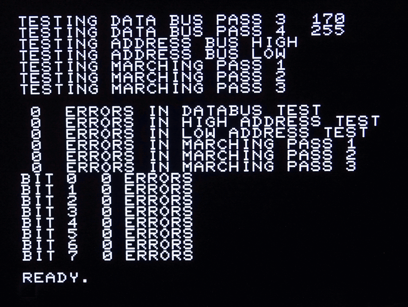
Testing
This version again went out to testers in late November 2016, and we all went through as many machines as we could lay our hands on, testing these to make sure they were as good as they could possibly be. Yes, that's an issue 1 Spectrum, yes, that's a divMMC Future prototype, yes, it's working.
We had a query about early
issue 2 board without the diode/resistor mod, and yes, it works on those as well, the issue actually coming down to the earlier boards (that didn't work with other divMMC boards) not having the 'Mandatory' clock modifications.
Does it work with the Harlequin Spectrum clone? It
should, but I didn't know, so I
built a Harlequin, and yes, it did work with with divMMC Future.
Also, since we no longer needed a clock signal, the Spanish 128K works fine with the divMMC Future. I have used it to test my
repaired Spanish toastrack, but wanted to be sure a stock machine would also work.
Thanks for Will Woodvine for the loan of a nice Spanish toastrack to prove this with.
By this point, all was looking good. We had a few machines that didn't work with any divMMC boards, even the divMMC Future. We couldn't have that. Further investigation revealed these machines had
Z80 chips with missing M1 signals, a new Z80 later and all was well.
I also wanted to give this a wide ranging test, so bought a selection of 'untested', 'working when put away' etc. loft find ZX Spectrums from ebay. In the main, these worked straight out of the black binliners they arrived wrapped in (many would say they should have remained in them). The few that didn't work straight away had grubby edge connectors, since these had been exposed to the elements for 35 years. After a clean, these also worked well, so was born the divMMC Future edge connector repair tool. (yes, it's a rubber, but it works quite well).
Continuing to go through as many machines as we could to prove this thing, I started resurrecting some scrap boards, including a
pretty ropey issue 2 Spectrum, and
a pile of grey Spectrum +2 boards, and anything that got as far as actually working, worked with the divMMC Future.
Quite late in the day, we also had a couple of machines which had issues that seemed to be down to NEC ROM chips. One turned out to have the wrong jumper settings (H=Hitachi, N=NEC, they have swapped OE and CS pins). The problematic ones did seem to have quite a large input current on the CS pin, which was stopping the ROM being disabled.
This could be proven by swapping the ROM for any other ROM chip, including later or earlier NEC ROM chips (I think the 1983 dated ones were the worst). A resolution for this was adding an extra transistor to the circuit to boost the pullup capability on the CS line, and that fixed that problem. This was the final change and the divMMC Future was ready for production.
Production
Throughout testing, we had some nice 3D printed cases (thank you Simpson Industries), which were great for protecting the boards during development and testing, but I don't think they could keep up with demand for production.
By this point, the injection moulds had been created, and the final cases had arrived. And don't they look smart.
In order to speed up production, I had built a
four gang programmer. This used four revived basket case +2 grey boards and allowed four devices to be programmed and tested in parallel.
Later a joystick tester module was added to automatically test all the inputs using a tester program loaded from the SD card.
With that, TFW8b went into production, and is still turning these out by the boxload.
To date, around a thousand units have been sold, and we have only heard of a couple of problems, and one of those was a +3 power supply failing (which also took out the Spectrum). So I think we did a good job. I think this is the best divMMC we could make. I hope you like them.
The divMMC Future is available from
The Future Was 8bit.
*Other divMMCs are available, but I wouldn't recommend them.