Friday, 29 March 2013

Nissan Leaf Review - Part 2: First Impressions

This is an old post, preserved for reference.
The products and services mentioned within are no longer available.

Just a quick update following on from the rather long first part of this review. One of the longest journeys I regularly make is a 34 mile round trip from here in Tynemouth to an office in Houghton-Le-Spring. I've been driving that route on and off for the last five years, so I know it well. All the little twists and turns, all the places here I need to change gear, and the places where I can get away without doing so. That makes it an ideal test for Nissan Leaf on motorway (type) driving, lets see how it does on that journey.

I have to say I've very impressed, it's so easy to drive. Just press the accelerator and it goes faster. Press the brake and it goes slower. It doesn't have to be any more complicated than that! It's so easy in fact, that I'm finding it easy to be going faster than I expect. I think I must be tuned to listening for the engine noise combined with knowing which gear I was in and subconsciously judging speed from that. One nice feature the Leaf has is a speed limiter, a bit like a cruise control, but just an upper limit, with no lower one. So, if my right foot is a little enthusiastic, it holds back and only accelerates up to the set speed, thus avoiding wasting energy by accelerating up to a higher speed, realising and then decelerating  It also benefits from gravity in the mode, so driving through the Tyne Tunnel, I set it to 40 mph and it was applying the brake automatically and recharging the battery via regenerative breaking all the time it was on the downhill part, the same on the long downhill stretch of the Houghton Cut at 50.

There are charging posts at my destination, so I plugged in my hard won Type 2 lead and charged from about 15% to full capacity in under 4 hours. During that time, I was able to monitor progress via the Nissan Car Wings website:
There is also an iphone app and an app for android (although it doesn't support android 4.x devices like my Nexus 7). Not all of the buttons on the site seem to be working at the moment, but I've raised this with Nissan and they're looking into it.

All in all, a very successful test. The range estimates I'm getting are a little misleading at times, I don't know how much of the driving history it bases it's assessments on, but it's going up and down all the time. I've already found I'm more comfortable with hard(er) facts like charge capacity. It seems that journey uses about 30% of the charge each way (the way I drive), so it's much easier to calculate based on that. There are 12 bars on the charge gauge, so as long as there are 4 bars left, I should get there. In practice  I'd be wanting 6 bars+ before setting off. Although I know if it is running low, just slowing down and turning off the aircon should extend the range sufficiently to get me there, and if it doesn't, there are a number of places I can call at on the way for a topup.

So much for a quick update.

2022 Update: The phone app and website are still a bit rubbish and still work intermittently. Which is a shame.

Wednesday, 27 March 2013

Nissan Leaf Review - Part 1: Actually Getting One

This is an old post, preserved for reference.
The products and services mentioned within are no longer available.

After almost 11 years, it's finally time to replace my trusty VW Golf GT TDI. This has served me very well over the last decade or so, and even though it's now 14 years old and still solid and reliable, it's time to upgrade.
I've looked around at various options and have become very interested in the possibilities of electric cars. It's a tricky subject to get decent information on, because there seems to be a lot of bad press on them, but really when you get down to the facts, it seems to be a combination of lazy journalism or lack of understanding.

The first thing everyone says when I mention electric vehicles, is 'what happens when you run out of charge on the motor way'. When you think about it, the answer is exactly the same as 'what happens when you run out of petrol on the motor way'. The answer is this, people point and laugh and you make an embarrassed call to a recovery service. The point is, you don't get into that situation. In a petrol car, if the low fuel light was on and the gauge was low, you'd think ahead and refill before making a long journey. It's exactly the same with an electric vehicle.

The main difference is that the overall range when full on an electric vehicle is in the order of 100 miles, whereas my teenage diesel could get in the order of 600 miles with 50 miles to the gallon. So, yes, it needs charging more often, but you can charge at home, at work, various car parks, and it costs between £0 and £3 per charge. As opposed to £70 on my golf. Given that information, if you plan to take long trips or drive more than 100 miles a day, an electric vehicle isn't for you. But if you're like the vast majority of us and you commute to work and back, 10 to 20 miles, plus trips to supermarkets etc. there's no reason to consider 'range anxiety' an issue.

So, my decision was made, an electric vehicle was a good choice for me, so all I I had to do was pick one. There aren't many choices at the moment, and the Nissan Leaf seems to be the best choice for me. There is a dealer close by, so I arranged a test drive and tried it out. It was fine. It worked, I was able to drive up and down the Coast Road without a problem. I didn't run out of charge. I didn't have to push it home. I didn't have to stop half way for a charge. It just worked. I don't have much experience of driving an automatic, but it didn't take me long to retire my left foot and left hand and drive only with the accelerator and brake (although I'm still subconsciously trying to check I'm in first when I'm waiting at lights).


I'm not the slimmest of drivers, but there was plenty of space inside, probably more than the Golf, even though it was about the same size externally (so it's 'bigger on the inside'). That's because there's just less stuff in an electric vehicle, the biggest item is the battery which is beneath the floor, the charger is behind the back seat, and the motor, transmission sit in the front where the engine would normally go. Also under the bonet is a standard 12v battery to power the lights and the radio etc.. That lot takes up much less space than an internal combustion engine, gearbox, transmission, exhaust, fuel tank, etc. This is front wheel drive, so there's a bit more going on, some of the older rear wheel drives were frighteningly simple and elegant with the wheels attached directly onto the motor shafts.


Having overcome what the press had said was the main issue (that of range), and my main issue (that of interior space), I couldn't see a reason not to get one, so I ordered one. Buying outright didn't seem the best option, and there is a potential issue of battery longevity. Nissan were quoting 5-7 years I think, and Renault had opted for a different solution and were actually leasing the batteries to the driver. Although it may be seen as a downside, all that will happen in reality is the maximum range will slowly reduce. It's not like a petrol car where when the engine goes, it goes at that's it. The solution seemed to be to go for a three year contract hire rather than an outright purchase. That gives me a good long time to try it out and see if it works for me. If it does, I'll be able to look around and buy a newer, faster, better, more version in three years time. Or a Golf TDI if it hasn't worked out.

That was what seemed to be the main objection out of the way, so it should all be plain sailing from then on.... Well, no it wasn't. I hit a few snags, the ones they don't tell you about when they're too busy driving around and around Lincoln waiting to run out of charge. I think most of these will be sorted over time, but in an emerging market, there are some teething troubles.

Firstly charging. That shouldn't be a problem right, that's one of the main functions of the car? Well there are essentially three ways to charge the Leaf. One is via a supplied charger which has a standard 3 pin 13A mains plug on the end and charges the car in around 8 hours (normally overnight). The second is to plug into one of a growing number of charging posts in public and office carparks, many of which have the new Type 2 Mennekes.sockets which with 32A will charge in about 4 hours. The third is to use a rapid charger, currently mainly installed at Nissan dealers, which can charge to 80% in 30 minutes. 

The 13A plug charger is supplied with the car. The rapid chargers have cables built in, much like a petrol pump. What's missing is the cable which connects the car park charging posts to the car. Nissan are apparently going to supply one in future models, but at the moment, they couldn't source one. I found one online and reluctantly ordered it (£200 for a cable!). After a week, no sign of the cable and the car delivery date approaching, I contacted them and found it was out of stock until some time in April - I wonder when they were planning to tell me that? I then searched further and found another lead from a different supplier, more expensive (£250 for a cable!!), but looked better with a longer flexible black cable as opposed to thicker bright orange. (and yes, it is thinner, but the conductors are still 6mm squared cable, so it is rated for 32A). That was in stock and was delivered the day before the car. So that one's sorted, and probably isn't going to be a problem for future purchasers.

The next issue they don't tell you about is insurance. It seems half of the insurers I called didn't have the Leaf listed or don't do electric vehicles (0cc? ok, but is it petrol of diesel?) and the other half don't insure leased vehicles. Again, I'm sure they'll get the hang of it over time.


It was quite a struggle in the end. It took a while to get the paperwork sorted and insurance setup, and after several days of emails, and phone calls, the Nissan dealers IT problems and three hours sitting in the dealership signing things, I finally drove away in my new Nissan Leaf. Being electric, there's no engine noise, only road noise and the depressing sounds of depreciation as a new car is driven off the dealers forecourt.

So I'll leave it there for this instalment  this is going to be an experiment, it might not work, but I think it will. Time will tell. There are only a few thousand electric vehicles on the road in the UK at the moment, so it's a bit new, but get over the few teething problems, and I think it's going to work. I'll continue this review over the coming months as I get to know the Leaf and report on my progress.

2022 Note: I think the experiment worked. I had to give that Leaf back after three years, and so I bought another new one, this time with an option to buy after three years, which I did, and I still have it, and it's still a great car. And I haven't run out of electric once.

Tuesday, 5 March 2013

How not to wire a plug

This is an old post, preserved for reference.
The products and services mentioned within are no longer available.

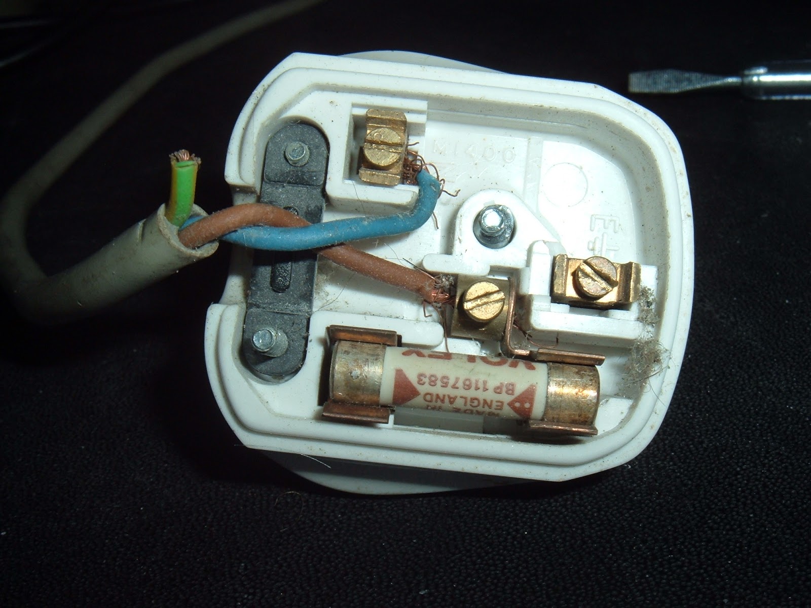
This was on something that came in for repair today. I think this must be the worst wired plug I've ever seen. The earth wire is cut off short, no where near the pin. The live and neutral wires are at least in the right places, but both have loose strands and aren't screwed in tight. The strain relief has been entirely ignored, and the fuse is 13A when the appliance uses less than 500mA.
Oh dear, it's a good job everything comes with moulded plugs these days!

Saturday, 23 February 2013

Sinclair ZX80 Repair

This is an old post, preserved for reference.
The products and services mentioned within are no longer available.

I've been doing a number of projects recently on the ZX81, and one of the things that comes up from time to time, is its predecessor, the Sinclair ZX80. This was a similar machine, in many ways the ZX81 is a cost reduced version of the ZX80.
The ZX81 had a new version of BASIC, with various improvements. It also had additional hardware to support fast and slow modes, which allow it to temporarily disable the screen display (which takes up most of the processors time normally) to allow the program to have full use of the processor.
Internally, the main change is the 21 chips in the ZX80 were reduced to 4 (or 5) in the ZX81, which together with the reduction in board size this brings made it much cheaper to produce than the ZX80. Apart from fast mode, the spec is largely the same, 1K RAM, 3.25MHz Z80 CPU. The ZX81 version of BASIC is in an 8K ROM as opposed to the ZX80's 4K. The other difference is the external case of the ZX80 seems to be made of the same stuff they make yoghurt cartons out of, making them very susceptible to damage. The ZX81 has a more sturdy case.
I've been after a ZX80 for ages. Recently, I decided it would be interesting to build one from scratch. That's progressing, but currently looks like this, so there is still a bit to do.
Work has been interrupted as I have managed to get hold of an actual ZX80. It was sold as 'not working', but I'm never put off by that on something that should be perfectly serviceable. One of the beauties of the ZX80 is that is it build from mainly standard parts (no ULA's), so any faulty parts can be replaced. A bonus was that this ZX80 was built from a kit, so the chips are all socketed, making that even easier.
Like many computers of that age, this one had been modified over time. The ZX80 had a wire link to allow white on black or black on white mode, this has been wired to an external switch and a hole drilled on the case for the switch (covered by the sticker on the top, below the vent).
Sinclair also released the ZX81 version of BASIC for the ZX80 (albeit without support for fast / slow modes). Some of the keys changed function, so it would have been supplied with a new keyboard overlay for ZX81 mode (which I don't have). This unit has both ROM chips fitted 'piggy backed' with two pins each bent out and wired to a switch to select which version to use.
One of the issues these computers suffered from was the dreaded 'RAM pack wobble'. The RAM packs plugged into the back of the unit to expand the RAM to 16K. The connector used was susceptible to being knocked (or sometimes someone sneezing nearby), which usually resulted in the computer resetting and losing all the work you'd been doing. Talking to the original owner, this had beren remedied by soldering the RAM pack on via a ribbon cable. This has since been removed, but that process had left a few small solder bridges between pins on the connector, presumably leading to the 'not working' situation. There were also some loose wires on the switch, which was stopping the ZX80 ROM working. I took the (difficult) decision to undo the ROM modification. The ZX80 version was the one I wanted, and so I removed and separated the two ROM chips.
The one of the left is the 4732, the original 4K ROM. The one on the right, the 2364 is the 8K ZX81 style version. Presumably due to height restrictions, the socket had been removed and the chips soldered directly to the board. I decided to fit a socket, I tried to find one of a suitable vintage so it didn't look out of place. With everything cleaned up, I tried it out, with the 8K ZX81 ROM which had been working. No problems, still working. It's easy to tell it's 8K BASIC as some of the keys are different. For example 10 PRINT "hi" is 1, 0, p, shift p, h, i, shift p on the ZX81, it's 1, 0, o, shift y, h, i, shift y on the ZX80. The font is also narrower on the later BASIC.
Next I tried the ZX80 ROM which hadn't worked before, and I'm pleased to say that now worked.
Below is the result of
10 PRINT "HELLO ZX80" 
20 GOTO 10. 
Apologies for the photo, I haven't done the composite video mod (and don't intend to), so it's on a CRT monitor. However, you can still just see the ZX80 is has a winder font.
So, one ZX80 restored to original condition. I've left it with the original 4K ROM, so it's now in permanent ZX80 mode. The 8K version is there if I want it, but I doubt I'll switch back to that since I have no keyboard overlay (and several ZX81s if I do want to use the later version of BASIC).
The next task is to build a 16K RAM pack for it.....

Sunday, 10 February 2013

Commodore VIC20 Repair

This is an old post, preserved for reference.
The products and services mentioned within are no longer available.

[UPDATE - VIC20 repair with 68766 EPROM]

I while ago, as part of a box of old computers, I acquired a Commodore VIC20. Specifically, the VIC20 CR (the 'Cost Reduced' version with the smaller main board and Commodore 64 style DIN power connector). Like the rest of the collection, it was a bit tatty and didn't work.
When powered on, it produced a black screen. It was producing a video signal, there just wasn't anything on it, no text, no border. Looking at the board, there was some corrosion around the pins of the two 6522 chips which drive the keyboard and the user port.
I removed the two corroded chips and fitted sockets - it should power on without these chips present (but obviously the keyboard and user port won't work. I tried it again but the screen was still black. A bit of tracing around with the scope showed the CPU wasn't clocking and was getting warm. I removed that as well, and fitted a socket and a known working 6502. Still black. The finger was now pointing at the chip which controls the video output, the VIC chip.
This was another of those custom chips which seem popular in machines of this vintage, they run hot, fail and are impossible to replace. It looked OK, and wasn't running too hot, but I didn't have a replacement to try. And there I left it for quite a while until I was able to get hold of a working VIC 20 motherboard to do some testing with. When I got the second board, I tried swapping the VIC chips, and it turned out they both worked. So the VIC was not guilty after all. Further probing found some of the data lines were being held low. This could have been anything on the bus, one several TTL chips, an assortment of RAM and ROM chips - the VIC, 6522 VIA's and the 6502 CPU had been ruled out. The VIC has three ROMs, the OS ('kernal' seems to be how it is spelled in all the documentation I've seen), BASIC and a character ROM for the display. The kernal is socketed, the others aren't, so I tried that first, and rather surprisingly it turned out to be the thing causing the fault. Normally 80's mask ROM's are pretty indestructible, I had the Sinclair ZX81 ROM from my very first computer on my desk for many years, and even with bent and missing pins, I managed to get that working when I was testing some ZX81 stuff last year.
I tried cleaning the pins and the socket and reseating the chip, but couldn't get it to work. The custom 901486-07 ROM is an 8K 24 pin device, and difficult to replace directly with an EPROM. The standard 8K EPROM is a 2764, which is 28 pin. The correct signals are there, just not all on the same pins, so I made an adapter out of a 24 pin DIL header and a 28 pin socket. Most of the pins are straight through, but a few of the pins have to be rerouted.
All I need then was to program the image onto the EPROM. At this point I could have built the reverse adapter and then read in the working ROM, but I cheated and downloaded an image of the ROM from the net. Burning an EPROM used to be a common task, I remember burning several sets of BIOS ROMs for early PC's network boot ROMs and many, many BBC Micro ROMs. But it has been a couple of years since I last did that. I reached for the box on the top shelf marked 'EPROM Programmer' and found my old programmer inside, together with my trusty EPROM eraser. It is actually a PSION datapak formatter, but it does the same job - expose the silicon to UV light through the window in the top to erase the contents (PSION datapaks were just EPROMs in a cartridge).
The programmer was a cheap Chinese one from ebay about 5 years ago, and that proved to be quite an issue.
Although there is a USB socket onboard, it's actually only for power and the data is transferred using the parallel port. Parallel port? Oh dear, doesn't look like any of these PCs have a parallel port anymore. I did have a parallel / serial PCI Express card, so I fitted that, found the drivers and tried the programmer software. No luck, I think it needed a 'real' parallel port, i.e. one on the motherboard, using one of the standard 278/378/3BC addresses. There were also issues with compatibility with modern operating systems. Eventually, I ended up dusting off (literally) an old Windows 98 SE laptop I used to use for this purpose. The software was still on there and seemed to work this time.
Takes you back eh? All I had to do then was get the image onto the laptop. Sadly 98SE had poor support for the fledgling idea of USB sticks, and doesn't support most of them, and no one supplies 98 drivers these days. Oh dear. I eventually ended up using a compact flash to PCMCIA adapter that I used for loading things onto my Amiga 1200, and finally copied the image onto the laptop. Once the image was on the laptop, it was just a case of burning the image onto the ROM. Installing the ROM into the adapter and installing the adapter into the VIC 20.
Fingers crossed, I turned it on.
Success! Now that was a lot more difficult than I had been expecting!


Thursday, 24 January 2013

ZX81 Acorn Electron Casemod

This is an old post, preserved for reference.
The products and services mentioned within are no longer available.

Today in the blog, I answer the age old question, "what do you get if you cross an acorn electron with a sinclair zx81?". The answer it seems, is a more usable ZX81.
Whilst having a clear out, I came across two things and thought, hmm, there's a project. The first was a ZX81 board. This was a working board extracted from a ZX81 which I was asked turned into a ZX81 USB Keyboard. Normally, I only use broken ZX81's for this, and there is unfortunately a reasonable supply of these. The vision of Sir Clive to reduce it all down to 4 chips left CPU, ROM, RAM and 'everything else' and it is these ULA's which contain everything else that are the problem. They run hot, and when they fail, the only source of spares is another ZX81. So if the ULA goes, you just get another one and all that can be done is perhaps turn it into a USB Keyboard or a door wedge. But in this case, I was sent a working '81 to convert, I was told I could keep the board, so once tested, I put it aside knowing one day I'd  find a use for it, possibly installing it in a new case with a proper keyboard.
It was a slightly odd Issue 3 board, in that all the resistors were raised up by 10mm. I can only assume this was build from a kit and the builder decided that was the way to go. Very odd. The ULA has some graphics card RAM heatsinks on it to help it run cooler. The other heatsink is the standard voltage regulator heatsink, which also runs warm. This is one of the cases where 'only 4 chips' actually means 5 as there are 2 RAM chips here rather than the alternate single chip.
The second thing I found was the result of a previous idea. I'd started with the premiss that you can never have enough Acorn Electrons, then argued that perhaps I had one too many. In fact, I had several with some things slightly wrong with them. One with a dirty case, one with a slightly twitchy keyboard, and one which had an intermittently faulty ULA (yes, Acorn fell for the same trick and put much of their glue logic into a single point of failure). So I shuffled things around into a pile of working electrons and one with all the bad bits. And this was what I found.
So the plan came together. I'd put rehouse the ZX81 board in the electron case. Making the best ZX81 system I could in there. There were four main things I felt I needed to 'fix' on the ZX81:
  1. The video output is through a UHF modulator and most modern TV's can't tune into it's signal. There are a number of standard mods to convert the output to composite video which most TV's can handle.
  2. The power supply. One of the old issues with the ZX81 was the power connector, and how easy it was in some circumstances to knock it and loose what you'd been working on. It also ran hot as it was a 7805 linear regulator running on 9V, so was dissipating about 4 Watts of heat.
  3. The keyboard. Ironically, since I'd converted a few into USB keyboards, they keyboard was a bit of an issues on the ZX81. The USB one I have on my media PC is for occasional use only (and because it looks better than an old PC keyboard). For longer term use, the membrane is a bit of a pain.
  4. RAM and storage. I bought a ZXpand a while ago and I would like to use that here. This adds 32K RAM and SD card storage, so solves both issues in one.
The video mod was easier than expected because this ZX81 had the later 2C210E ULA which produced a better signal (it included the back porch pulse which was missing on the earlier versions).
All that was required was a transistor buffer to get the signals to the right levels. As with many people, I fitted the circuit in side the modulator case. I found a bit of variation in the resistor required between a few TV's I tried. The standard circuit uses 100 ohms, but 75 ohms would be a better match for the input resistance, and indeed worked better in some cases. In the end, I installed a 220 ohm variable resistor which can be adjusted through the old tuning hole.
The next challenge was the power supply. I wanted to replace the 7805 regulator as I planned to expand the system, so needed more power and it already runs hot with the standard load on. I had considered using a mains power supply, housed inside the case, but I had some issues with height, so went back to the electron supply. This was unusual in the it was a switched mode supply which ran from 19V AC and generated 5V and -5V. Almost right. A bit or modification, and it now runs on 12V DV and provides 5V for the ZX81 around 11V for the add odds (the unregulated DC is passed to the ZX81 expansion connector to add on units don't overload the onboard regulator). The 7805 was removed and replaced with a 3 pin connector.
The keyboard was always going to be interesting. I'd looked at a few options in the past, but the way the ZX81 worked made that difficult. It has 8 rows and 5 columns, with the rows split in the middle, so 1-5, 6-0, Q-T Y-P etc. The 8 rows are actually the 8 higher address lines, and the 5 columns are inputs to the ULA. The addressing scheme meant that it was read on every other input address. So the lines were scanned by setting the higher address lines and reading the 5 inputs. Any which were pulled low were considered pressed. The electron was 4 lines of 16 inputs, but was made of individual mechanical switches on a single sided PCB, so it was fairly easy to cut tracks and rewire it to the ZX81's matrix. I was even able to extract things like Delete out to a separate key (it is SHIFT+0 on a ZX81 and is called 'Rubout') by using additional diodes connecting to the rows of SHIFT and 0 as they were on the same column.
That's about as far as I've got. This is sort of work in progress as there are a few things to do. The ZXpand is unfortunately too big to fit in, I need to look at other options to fit it in, or just add 32K RAM on board. I also need to clean up the case, possibly spray it back, and look at making stickers for the keycaps.
But as it is, it's a ZX81 with a decent keyboard, proper video out and a stable power supply. I couldn't resist a final test program, and it had to be.
10 PRINT "TYNEMOUTH SOFTWARE BLOG"
20 GOTO 10
Now, where did I put the 3D Monster Maze tape?

Friday, 18 January 2013

Tiny LED Clock

This is an old post, preserved for reference.
The products and services mentioned within are no longer available.

Now that I have finished the new circuit for the old LED clock and that was running nicely, I got to thinking that the ATMega328 used in that was overkill, 18 pins, most of which were unused. I'd gone with that as it was fairly simple to use an Arduino for development. But back in the simple LED clock all it was doing was reading I2C from the RTC and writing it to the LED display using the same I2C bus, and that only took two pins. I decided to have a look at the ATTiny45, an 8 pin device which could do I2C. I rigged up a test circuit with the Arduino ISP programming the ATTiny45 (using the approach suggestedby high-low tech).
It looks a bit like an ode to the flying spaghetti monster, but basically, the orange wires are the ISP connections from the Arduino, running the ArduinoISP project (the capacitor is needed on UNO boards to stop the Arduino resetting). The rest are the black and red of power and the white and green and the I2C clock and data to the Adafruit RTC module and LED display. It all looked promising until I clicked build, as unfortunately the wire library used for I2C comms on the Arduino isn't supported on the ATTiny range.
I found the TinyWire library, which did provide I2C support on the ATTiny range, but the RTC lib and the Adafruit display libraries used wire and didn't work. The example which came with the TinyWire actually used the DS1307 RTC, but just made the call to read and processed the BCD response in the main code. That approach was all I really needed there for the RTC. The display was more of an issue as there I couldn't used the Adafruit library code. However, I had found a slight issue with that. Only slight, it only had a problem between 23:59 and 1:00. Basically the time is converted into an integer as hours x 100 + minutes, so 23:59 is just 2,359. The trouble comes with midnight. This adds up to 0 and so the display just shows '  :  '. A minute later we get '  : 1', nine minutes after that we get '  :10', and so on until '  :59' is finally followed by ' 1:00'. So I decided I could get around that be extracting the bits of the library I needed and converting them to use TinyWire rather than Wire, and in the process ensuring I left leading zeroes where required.
So finally, I ended up with a very simple circuit, but more complex software. I made the finished board the same size as the LED display, which sits on top. I could have used a smaller button cell, but the CR2032 is ubiquitous, and I had spare holders and cells, and it just fitted in the space. The only other components are the decoupling capacitor, pull up resistors for the I2C bus and the 32.768KHz RTC crystal.
One downside to this approach was not being able to set the RTC without writing mode code. I went with the easier option of installing the battery, then wiring up the I2C bus (without the ATTiny45 installed) via the display connector to an Arduino. This ran some simple code which set the RTC to the PC clock. I then disconnected that, installed the ATTiny45 and the Adafruit LED baclpack and the unit was complete.
I've wired this to a USB cable, and it now shows the time next to my PC. When the PC is off, the power to the USB goes off and so does the display. The RTC maintains the time thanks to the battery, and next time the PC is switched on, on comes the display with the right time on it.