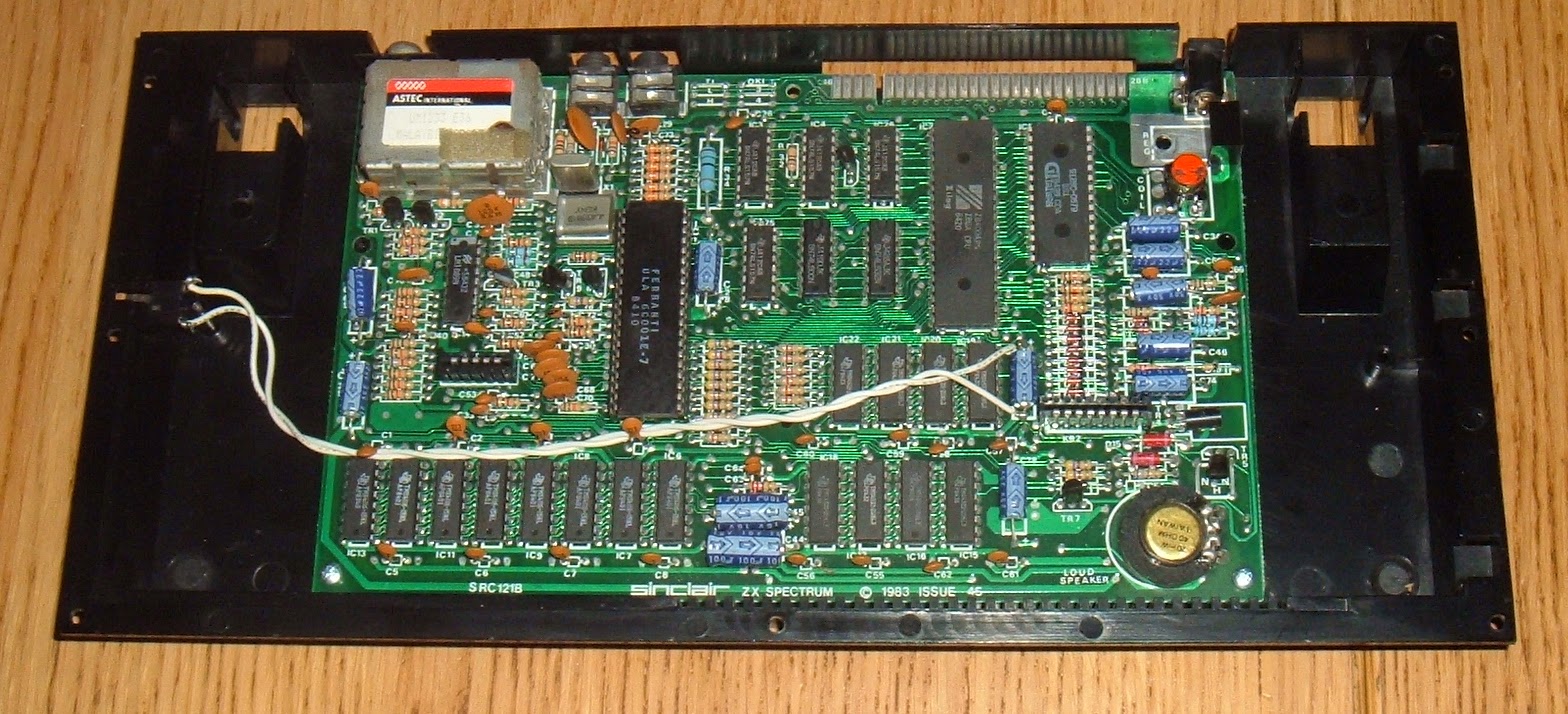
One of the things the Sinclair ZX81 and ZX Spectrums were known for was getting rather warm. If you (carefully) open one up, you'll see where the heat comes from.
This is a Spectrum Plus, but it is the same board as used in the original rubber keyed ZX Spectrum. The big lump of metal at the top is the heatsink.
The original circuit uses a 7805 linear regulator. The input for the Spectrum is marked 9V, although most of the Sinclair supplies give around 12V output. The current used depends of the version of the ULA, the manufacturer of the RAM etc, but is around 650mA. Original Spectrum's came with UK700 model supplies (700mA), later ones with UK1400, 1.4A supplies. The regulator is rated 1A, and generated 5V used by the chips on board. The -5V and +12V used by the RAM and video circuits are also derived from the input supply. This is a purely linear shunt regulator, so 5V at 1A is used by the board and eventually converted to heat by the chips (usually the ULA gets the hottest unless something is wrong). The rest, up to 7V and 1A is converted to heat in the regulator, so there could be 7W of heat dissipated by the heat sink, hence why these things get hot. This works out about 40% efficient.
This is a Traco Power TSR 1-2450 switch mode replacement for a 7805. It takes in the DC in and generates 5V DC out using a switch mode power supply design. This is around 90% efficient, and so generates little heat. It also puts less strain on the power supply unit as it draws around half the power of the original for the same output. (7805, 12V @1A to get 5V @ 1A, TSR1-2450, 12V @ 400mA to get 5V @ 1A). The same Spectrum that used about 650mA dropped to 400mA with the new regulator.
These modules are drop in replacements, so just remove the 7805 and metalwork, and install the switch mode unit. You now have a much cooler running Spectrum.
Usually a good idea at this point to reflow the solder on the DC jack as they can start to become dry joints over time. Even replaced the jack if the connector is tarnished or worn looking.
The same approach can be used on many other devices of that era which use linear regulators and big heatsinks. The ZX81 and Spectrums, the Atari 2600, the NES, most of the Commodore computers etc.
I use one on my Spectrum test rig as removing the heatsink also gives easier access to the chips behind.
Since this was used without a lid, I used the hole where the heatsink had been bolted to add a power LED.
Update: You can use the same things on the ZX81
And SNES
Sunday, 9 November 2014
Saturday, 1 November 2014
USB to 1541 Adapter
This is an old post, preserved for reference.
The products and services mentioned within are no longer available.
The most popular of the Commodore drives is the 1541. These things are about the size and weight of a concrete breeze block, mainly due to the internal linear power supply.
Inside there is a 6502 processor, two 6522 VIA's, 2K RAM and 16K ROM. This has a custom drive controller chip, rather than the VID video and sound chip, but otherwise not for off the spec of the VIC20 computer. The serial bus connection has a rather useful benefit, without too much work, the serial protocol can be implemented on another computer, giving full access to the drive.
This was done many years ago on the PC, and simple parallel port adapters gave access to the drives. I've build a few versions of the X cables over the years. This is quite a nice little XA1541V2 board I picked up this one on ebay a few years ago. It has transistor drivers to boost the drive capabilities. The only problem with these is the lack of a parallel port on modern computers. I have an old XP laptop I keep for this sort of task, which has built in parallel and serial ports.
I have a few disk drive projects coming up, so I wanted to get this up and running again, ideally on my main development computer, without a parallel port. I looked at various options, including a pci express parallel card which didn't work too well, it seems the older the better for this task. I also looked at USB-parallel options, then thought why not cut out the middle man and drive it direct. Turns out, this too has already been done. xum1541 is a USB to 1541 interface, and ZoomFloppy is an nice implementation of that. I don't know if these are still current, these seem to date to 2011. All the information is there, so I set about building one.
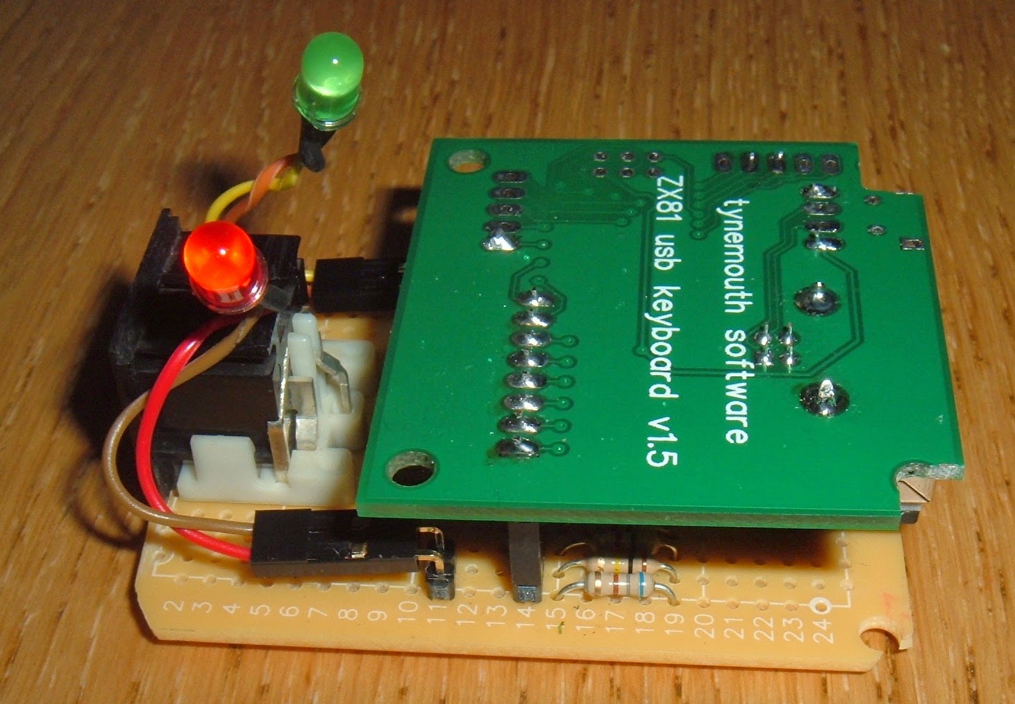
This chip used, an ATmega32U2 is the same foorprint as the chip I used on my smaller USB keyboards, so I adapted one of my ZX81 boards for this purpose. It had all the USB interface and the crystal etc, so that was the USB side sorted. The firmware was loaded using the Atmel Flip interface, as I think was the plan with xum1541.
The IEC side is similar to the output stage of the Commodore computers it was designed to talk to, so in a slight change to the design, I used a 7406 chip. The red LED is activity, I later added a green power LED on the right.
Those two sandwich together to implement something like the xum1541. The design can also include a parallel connection to the 1541 drive to speed it up, I'm not adding that at this stage as I don't mind it running a little slower. There is also the option to talk to IEE488 drives, which is something I'm going to be looking at next, I have an 8250 drive to refurbish to go with the Pet.
That all fits nicely into a small box, firmly held in place with too much hot melt glue as usual
With that complete, the 6 pin IEC cable connects to the drive and the USB side to the PC. Time to fire it up. As usual with IEC devices, best to connect everything up, then power on, drive first then computer. A good way to fry the 7406 chips is to plug the drive into a Commodore 64 when powered on. In this case, connect to the drive, power on the drive, then plug in the USB.
The software I used with the parallel cable was a collection of command line utilities, opencbm. These are still there, and still work. This is cbmctrl, which is used for sending commands to the drive such as reset, status and directory.
But things have progressed, and there is now a nice user interface which uses these programs behind these scenes. This is CBMXfer.
Very nice to use, this also ties in a number of other tools such as d64 disk image creation (disk to image and image to disk). There are also tools to view source files, with the basic tokens correctly displayed.
And integration with vice, the commodore emulator, so you can run the files you have just transferred or are about to transfer to check them out.
There are a number of elements involved in this process, and this is the work of many different people. All credit to them, and I am grateful to them all for making it available, it's going to be very useful.
Labels:
1541,
Commodore,
Disk Drive,
USB
Sunday, 26 October 2014
Commodore 128 Repair - Part 4 Commodore 128 Modes
This is an old post, preserved for reference.
The products and services mentioned within are no longer available.
It's a bit of a strange beast the Commodore 128, two CPUs, two video processors, four types of memory, three operating systems and two versions of BASIC. Not bad for a single computer.
The default mode on power on is Commodore 128 mode. This has 128K RAM and BASIC V7.0 and uses the 8502 processor, based on the same 6502 as the Commodore 64's 6510 and the 264 series 7501. The default is 40 column mode, it can also work in 80 column mode, but you need to connect the monitor to the 9 pin D connector, rather than the normal 7 pin DIN.
If you type GO64, or hold down the C= key on startup, it goes into C64 mode.
This is limited to 40 columns, and 64K of RAM and runs BASIC 2.0, as did the Commodore 64, again using the 8502 processor.
The third mode, uses the Z80 processor to run CP/M. To use this, you need a CP/M system disk in a 1570 or 1571 disk drive. I don't have one of those at the moment (watch this space), so I'm loading the disk image from an SD2IEC.
This loads up (after a while) into CP/M version 3.0.
It also works in 80 column mode.
That's quite a lot of options.
- 40 Column Commodore 128 mode
- 80 Column Commodore 128 mode
- 40 Column Commodore 64 mode
- 40 Column CP/M mode
- 80 Column CP/M mode
I wonder how many C128 owners used all the modes?
It seemed compulsory in the Commodore PET repair articles to show space invaders, so why not continue that, here in an 80 column Commodore 128 version.
Labels:
C128,
Commodore,
Repair,
Restoration,
Vintage
Saturday, 25 October 2014
Commodore 128 Repair - Part 3 Testing
This is an old post, preserved for reference.
The products and services mentioned within are no longer available.
Nice to start off with a working board for a change. One of the things the C128 offers is 'full' C64 compatibility, so I tested it with the Commodore 64 Diagnostic Cartridge and Test Harness.
This shows an error on the user port, even after swaping over the two 6526 PIA chips the error stays on the user port. I also tried two known working chips with the same results.
I've seen this problem on a couple of Commodore 64's as well, I think it may just be an issue with the test algorithm or the loopback, but I've seen it pass on enough machines to know it is wired up correctly and the PIA chips do work.
I've cleaned the contacts and checked for loopback continuity. I think I'll build something with LED's on and a simple BASIC test program to be sure.
This is only testing the lower 64K of memory, all that is visible in Commodore 64 mode. There are Commodore 128 Diagnostics, but I haven't had much success with those. I've found three versions, all 8K cartridge images, so I programmed the latest one in the same way as I had for the other carts, onto an MCM68766 EPROM.
That sort of worked, but not particularly well. All the external tests failed? I'll come back to this at a later date.
So there is the Commodore 128. Time to give it a bit of a run through and try out all the modes.
Labels:
C128,
Commodore,
Repair,
Restoration,
Vintage
Thursday, 16 October 2014
Commodore 128 Repair - Part 2 Keyboard
This is an old post, preserved for reference.
The products and services mentioned within are no longer available.
The keyboard is not in too bad condition, it needs a good clean, and there is some yellowing to the keys (apart from Run Stop for some reason). Sometimes if the odd key is not working, repeatedly pressing it can bring it back to life, but the best option is to clean it properly. The procedure is the same as the Commodore Vic 20 / 64 keyboards, a few steps less than the cleaning the keyboard on the Commodore Pet.
The keys are removed using a key puller, trying to avoid the springs going everywhere. The keyboard has two additional smaller springs, so keep these separate. The box of keys can then go off to be washed in hot soapy water.
Shift Lock, Caps Lock and 40/80 Column are mechanical latching switches, and are wired separately to the back of the keyboard.
Theses need to be desoldered before the PCB can be removed.
The PCB is held on with dozens of tiny screws, remove those, but keep the frame down of all the plungers will fall out.
The contacts on the plungers and the PCB can then be cleaned with contact cleaner.
The principal of the keyboard is fairly simple, the PCB has two carbon covered pads for each switch.
The plunger is held up by a spring, and when pressed down, the pads on the bottom of the plunger connect the two pads on the PCB together and the computer registers the switch pressed.
Whilst the principle is the same as the standard C64/VIC20 keyboard, the C128 keys are about half the height.
With the PCB cleaned and reinstalled and the switches soldered back on, the base is cleaned up.
Once the keys have dried, put all the keys and springs back on.
Be careful with the screws when reinstalling in the case. Some of them have spacers in place to stop the screw going through the front plastic. The original screws were a bit tarnished and the spacers a bit fiddly, so I just went for some shorter screws.
Subscribe to:
Posts (Atom)