Thursday, 11 September 2014

Commodore PET Repair Part 9 - Building a 4032

This is an old post, preserved for reference.
The products and services mentioned within are no longer available.

This is the ninth part of the repair and restoration of a Commodore Pet 4032. This is where it is all coming together. To recap from way back in Part 1, this early 1980's Commodore Pet 4032-32N computer has not been a Commodore Pet for probably 20 years.
When it arrived here, it had a PC installed inside it. The original board, had failed and been removed so I didn't have it. Last year, I removed the Pentium 75 board and tried various options for turning it back into a useful computer, and for a while, it ram a Z80 CP/M system. However, it should be a Commodore Pet, so I looked around to replace the missing parts. Parts being in short supply, I ended up getting them from a couple of different computers. Now everything is complete, time to put it together.
The bottom part of the case was a little rusty and have a few additional holes added from the PC board. I sanded this down and resprayed it.
Now that's nice and shiny, time to add the power supply I refurbished back in Part 2. This was partly from an 8032-SK, with the bracket from an 8250.
The capacitor is tied down to a couple of cable tie mounts. I think these would have been riveted originally, but I've bolted some on instead.
Next comes the main board. This originated from an 8032-SK that was incomplete, rusty and had some cosmetic damage.
Various problems have been fixed on this board, including various corroded components, dodgy sockets, broken tracks, faulty 6520, 6545, 74LS00x2, 74LS74, 74LS244x2, 74154, 8x4116, 1xmask ROM (901474-04). See Parts 3, 4, 5 and 7. It was originally an 80 column board, but was converted to 40 column to match what would originally have been fitted, back in part 6.
That's all looking good.
Nice to see the edge connectors sticking out at the back. Probably 20 years since this had working Pet board in it. Next, the top case needs a bit of a clean.
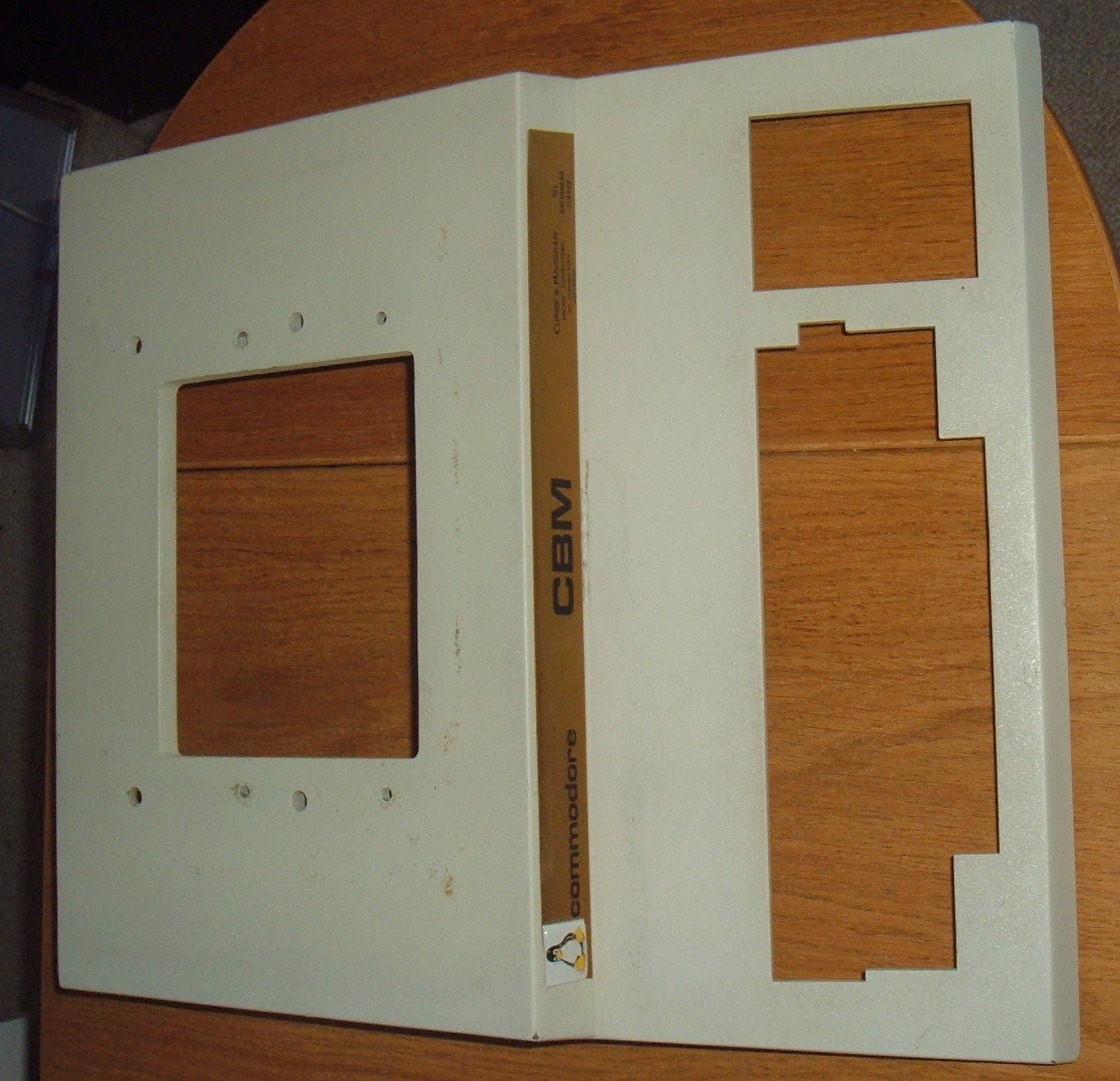
Now I remember why I put that tux badge there, the label beneath was damaged.
Not sure what to do about that. For the moment, I've carefully removed it cleaned the rest of the case. Now to install the keyboard that was refurbished in part 8.
One of the unique features of these computers is a car bonnet style case prop, which allows you to hold open the lid.
That's the base and the lid done.
The hole on the top is for the monitor, and the cables run through that.
Now for the monitor, but it needs a bit of a clean first.

Saturday, 6 September 2014

Commodore PET Repair Part 8 - Keyboard Restoration

This is an old post, preserved for reference.
The products and services mentioned within are no longer available.

This is the eighth part of the repair and restoration of a Commodore Pet 4032, you might want to start way back at Part 1. The story so far, an 8032 board has repaired and converted to a 4032. I am now in the process of putting it all together. The keyboard needs a bit of a clean.
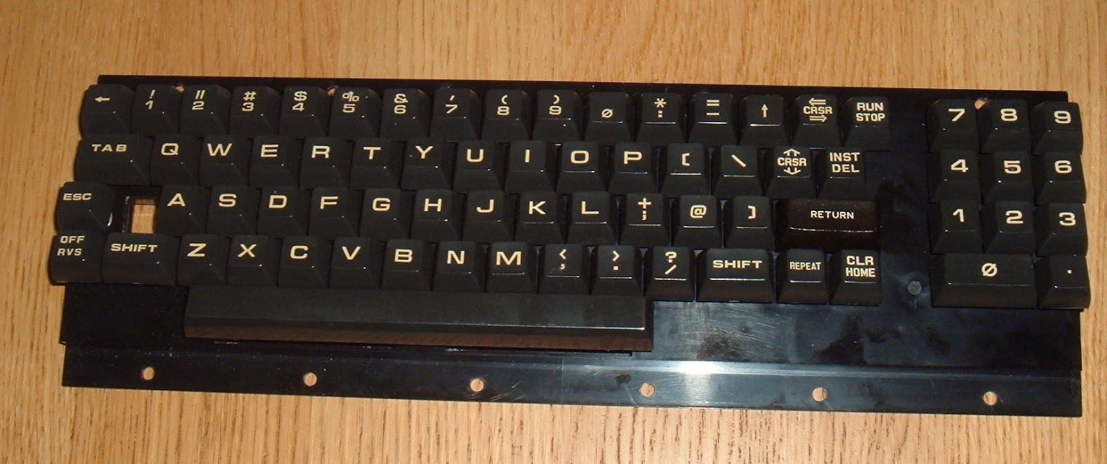
This is the keyboard as is. It is the 'N' for Normal or Graphics keyboard. Notable for the lack of numbers on the top row. Most of the keys are working, but some need a bit of extra pressure and a couple aren't working at all. This is a common problem with the sort of keyboards. The repair procedure is fairly simple, but is a bit tedious and repetitive. So for some reason, I've decided to tackle two of them at once
This second one is from an 8032-SK. This is the 'B' for Business Keyboard. The case is pretty bad, but the keyboard look like it will clean up ok apart from the missing return key. This layout is more normal with numbers on the top row and the smaller numeric keypad, and shift used for symbols.
Step one is to remove the rear PCB, to do this, the connections to the shift lock switch need to be desoldered
Once that is done, and 30 small screws removed, the PCB can be removed.
All this needs is a bit of contact cleaner. Next is to remove the keys. For this I use a key puller.
This slides down the sides of the keys, then you twist it 45 degrees and can safely extract the key vertically without damaging it or it's neighbours.
From the back, you can see how the plungers fit into the frame.
This is the tedious bit as each one needs to be carefully removed without loosing the spring.
Each one is made up of 4 parts, a spring to hold the key up when not pressed, a plunger with a carbon pad on the end to make the contact on the PCB when it is pressed, an adapter which plugs into the plunger, and the keycap itself. Some of the keys come off with the adapters intact, others separate. I don't normally split the intact ones.
These are separated, and the keycaps washed.
A nice clean set of keycaps.
And a cleaned chassis. Now, all that remains is the task of slowly putting all the keys back. You could arrange the keys in the correct order (you did take a photo of how they were arranged before you started right?) and put them in one by one. I prefer the riskier and more exiting pick a random key out of the box, and work out where it goes.
So far I haven't made any mistakes.
Although the letter O and zero keys threw me a bit. It's only on the sides they look different.
Once that's all done, double check they are all in the right place.
Then it's back on with the PCB and resolder the shift lock switch. Plug it into the pet and test the keys.
The procedure for the B keyboard was the same, apart from the return key. When I got it, the plunger was there, but the return key and adapter where missing, I looked through my spares, but didn't have anything suitable. These Pet keyboards are the only ones I have with these sort of stems on the keys.
The closest looking key I found was a BBC Micro Return key. This was the right size and colour - it looks a different colour under the camera flash, but to the naked eye, it looks fine. Here compared to the zero key from the keypad which is the right shape and size.
Here I've used the plunger from a Commodore 64 keyboard which has the same cross pattern at the top as the BBC, and was about the same angle from the top of the key.
With that cut down and the slot filed in, it looks a reasonable match.
In place it works rather well, the flash again making it look grey versus brown.
Better without the flash. Not perfect, but perfectly usable.
So that's two keyboards cleaned and ready to go. Now I need to sort out the case of the 4032...

Update: I've built some USB keyboard adapters to make testing easier - Commodore PET USB keyboard / Keyboard testers

Monday, 1 September 2014

Commodore PET Repair Part 7 - DRAM repairs

This is an old post, preserved for reference.
The products and services mentioned within are no longer available.

This is the seventh part of the repair and restoration of a Commodore Pet 4032, you might want to start way back at Part 1. The story so far, the 8032 board has been converted to a 4032 and most of the issues are now fixed, however I am still using the ROM and ROM replacement plug in board to replace the RAM. I now need to fix on the onboard RAM, so it can run on it's own.
The PET has 16 x 4116 DRAM chips, providing a total of 32K RAM. Of these 16 chips, two had been replaced in the past, and the replacements had corroded as the contacts of fetching red sockets went rusty.
Some of the others were corroded, and there was some damage to the tracks below those two replacement sockets. I initially replaced the sockets and the damaged DRAM and I tried to power on without the ROM/RAM board. But got only a blank screen, or rather a bright green dot as the CRTC had not been initialised. So the system wasn't running. Returning the ROM/RAM board, and switching to the test ROM on there, I could see all 'G' for good on the ROM/RAM board RAM and when I switched that off, all 'B' for bad for the onboard RAM.
It's only testing the first 1000 bytes of RAM (40x25), but that's all it should need to boot, and the result is fairly clear. The original Pet's used static RAM, 6550 and then 2114 chips, with 2 chips per 1K of RAM. This means you could remove all but two RAM chips and get it running. Not so for 'dynamic' Pets such as the 4032 here. It uses 8x 4116 chips per 16K RAM, so you need at least 8 working chips to boot. The way the Pet is organised, these alternate, so the lower 16K is UA5, UA7, UA9 up to UA19, and the upper bank is UA4, UA8, UA10 up to UA18. Checking the signals on these chips, it appeared the RAS0 line wasn't being set, and that was tracked to a flip flop, UE1.
That turned out to be a faulty 74LS74, with that replaced, RAS0 was now correct, but it still failed the RAM test. So all the right signals were getting there, must be the RAM chips. Some of the chips were running hot, so I removed and replaced those, and still nothing. I removed another couple of chips to test a sample of those remaining.
This is my 4116 tester, it's a beat up ZX Spectrum board with a socket on one of the DRAM chips. The board was fried when I got it, the ULA, CPU and ROM were all dead and surprisingly only one of the RAM chips. The damaged chips were all socketed and replaced, and it became a spare board, and later I used that it to test a ULA and later again some 4116s. I decided it may be useful for to use as a test platform so add a ZIF socket for those. The 7805 has been replaced with a small switch mode module to improve access (and reliability, and reduce heat etc.). It also leaves a hole where I fitted a red LED to indicate power on.
I think this board came from a Spectrum plus, the ugly blob of solder on the right is where the original reset switch was connected, the white switch is now reset. A switch at the side changes between the normal Spectrum ROM, and a RAM test ROM. It's actually one for testing 128K Spectrums from Paul Farrow.
The higher RAM tests fail, but the lower 16K test is still useful. The Spectrum uses 8 x 4116 as 16K of lower RAM and screen RAM, so if this RAM is not working, you get garbage on the screen. The test ROM sets lines on the border. Here 8 lines mean bit D7, which is the one in the socket.
It may not be an exhaustive test of the lower RAM, but it's good enough to weed out the duds. One of the two chips I removed passed the test, the other failed, so I removed the rest to test them all. Out of the 16 chips, two had been replaced already, and the replacements both failed. Two were corroded too badly to test. Two ran hot, so I assumed they had failed. I don't usually test those as if they bring down one of the three supply rails the 4116 needs to run, it could damage the other chips. That left 10. Two of those failed the test. The other 8 were OK.
These chips, along with a number of the other logic chips on the board had unusually short pins. These pins don't stick very far out of the board, which makes them difficult to desolder, and they don't sit will in sockets. In the end, I put those aside and used 16 known working chips, some MOSTEK branded ones seemed appropriate as that was what was originally fitted.
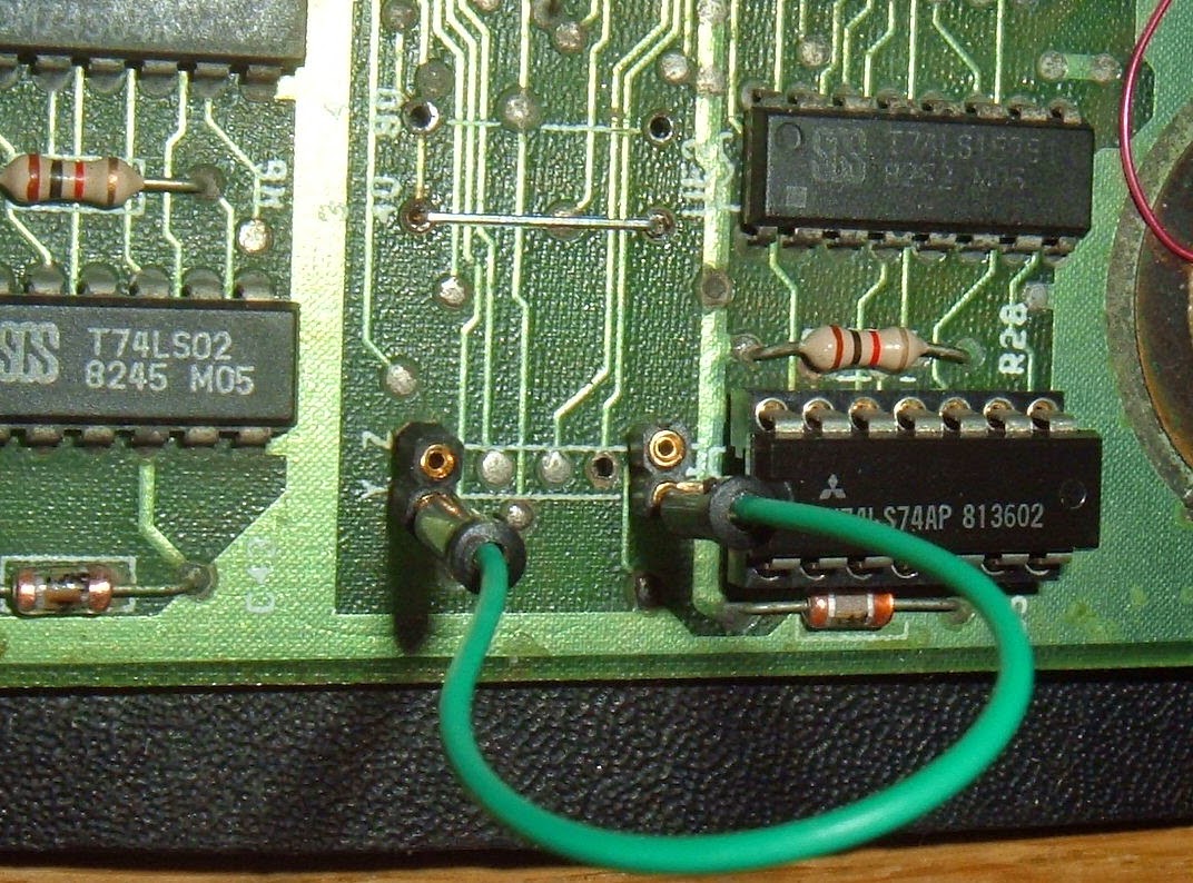
With those in, I still got nothing. An old trick for testing these is to switch the banks around. Both are wired in parallel bar pin 15. All the upper RAM chips have this wired to CAS1 via R11, and the lower chips have pin 15 wired to CAS0 via R10. (By lower RAM, I mean bank 0, 0x0000 - 0x3FFF, not the chips with the shorter legs). Swapping the connections makes the upper bank the lower one, and vice versa.
I temporarily added new resistors with long legs and sockets so I could swap them around.
The Y and Z jumpers can be used to change the RAM size, Z is 32K, Y is 16K, with the upper bank disabled. This allows the two banks to be tested separately. I got nothing with the lower bank, but when I swapped them, the upper bank appeared to be working.
That's better all G's. I gave it a go and it booted up in 16K mode.
That was good to see, so we are getting there. In order to check it wasn't the RAM chips, I swapped the chips between the two banks, but still the upper one worked and the lower failed. I eventually tracked this down to a broken connection under UA15, where one of the red sockets had been.
With that fixed, both banks were working again. I still had them swapped, so I reinstated the two resistors and the link, and finally removed the ROM/RAM board and installed a 6502. I now have a working 4032. It seems compulsory at this stage to test with space invaders, and all seems well.
It doesn't come out that well with my photography, but the screen is really crisp and clear, and a simple game like this looks great.
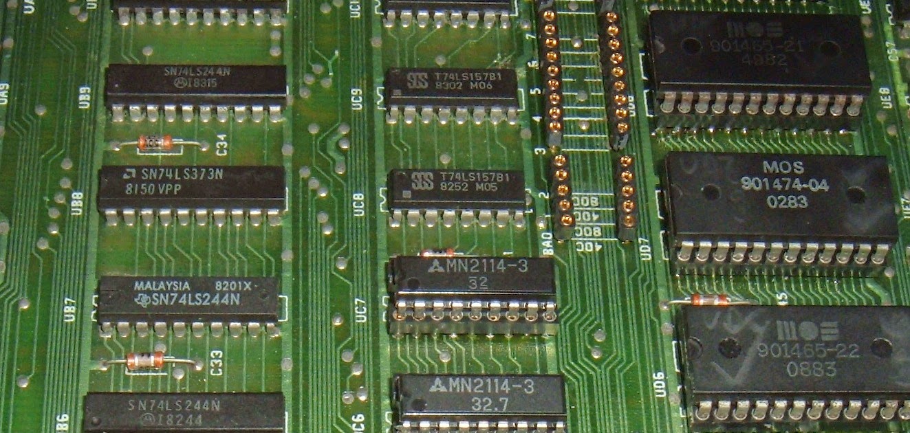
Whilst running that for a while, I noticed one of the 373 latches, UB8 was getting hot. This is one that isn't required in 40 column mode, so shouldn't be active. It wouldn't have been fitted on the 4032 models, so I took the opportunity at this stage to have a bit of a tidy up and removed the five chips (UB6-8, UC6-7) that wouldn't be fitted and made the 4032 mod permanent.
It seems to have taken quite a while to go from this..
to this..
But it's finally sorted. Now this needs to be put into the case, but first I think the keyboard needs a bit of a clean.